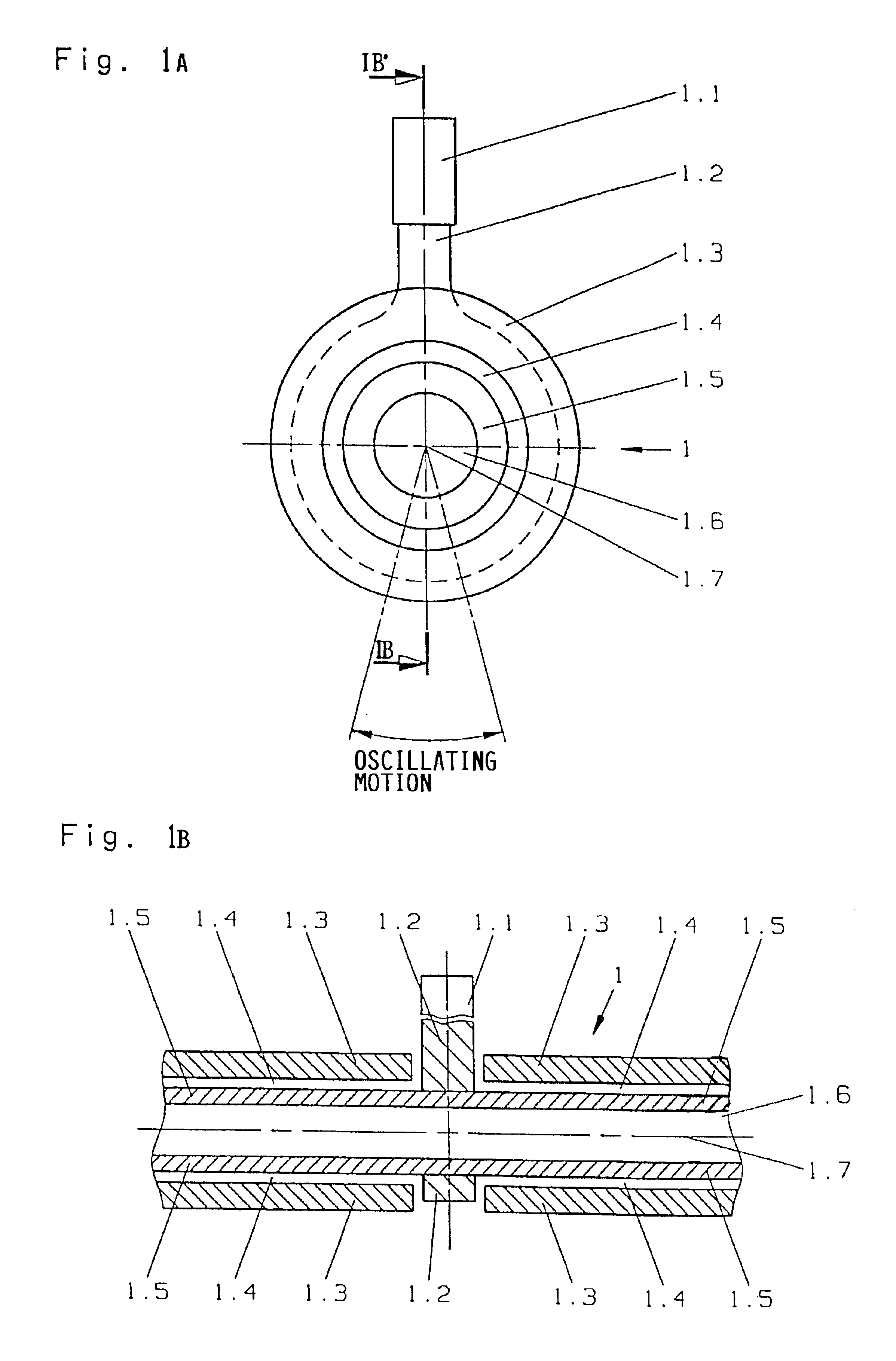
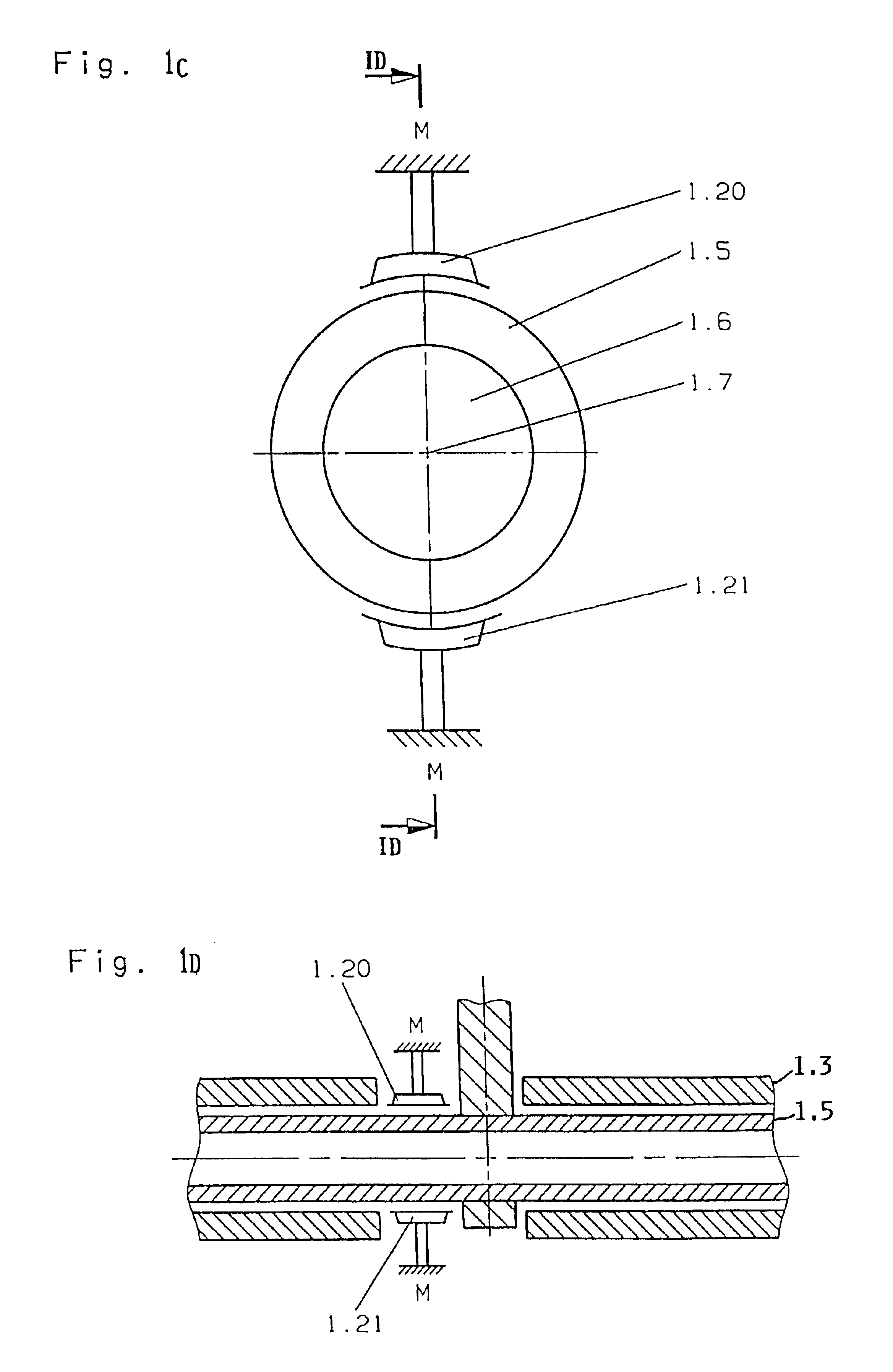
[0011]According to one feature of the first embodiment of the invention, the reed support shaft is embodied as a hollow shaft, so that the radius of the shaft may be significantly increased in comparison to prior art solid shafts, without significantly increasing the mass inertial moment thereof, because the mass of the hollow shaft will be correspondingly less than that of a solid shaft made of the same material and having the same outer diameter. Simultaneously, by displacing the mass to a greater radial distance from the rotation axis, i.e. in the annular wall of the hollow shaft, an increased strength-to-weight ratio of the shaft is achieved.
[0012]In one embodiment, the reed support shaft serves directly as the rotor of the electric motor direct drive, and particularly, is arranged as an internal rotor that is located radially inwardly from the stator toward the rotation axis. In such an embodiment, a substantially larger air gap surface or active surface is achieved between the rotor and the stator when using a hollow shaft with a larger diameter in comparison to a solid shaft with a smaller diameter. As a result, the inventive arrangement achieves a large effective driving force in comparison to an internal rotor motor having a solid shaft rotor with the same mass inertial moment as the inventive hollow shaft rotor. Simultaneously, the increased radius of the hollow shaft in comparison to that of a solid shaft of the same mass provides a larger radial lever arm or effective factor for the rotational moment or torque that is to be applied, because the torque is given by the product of the force and the radius. Thus, the rotational moment or torque that can be developed increases, in total, quadratically with the increasing radius of the shaft.
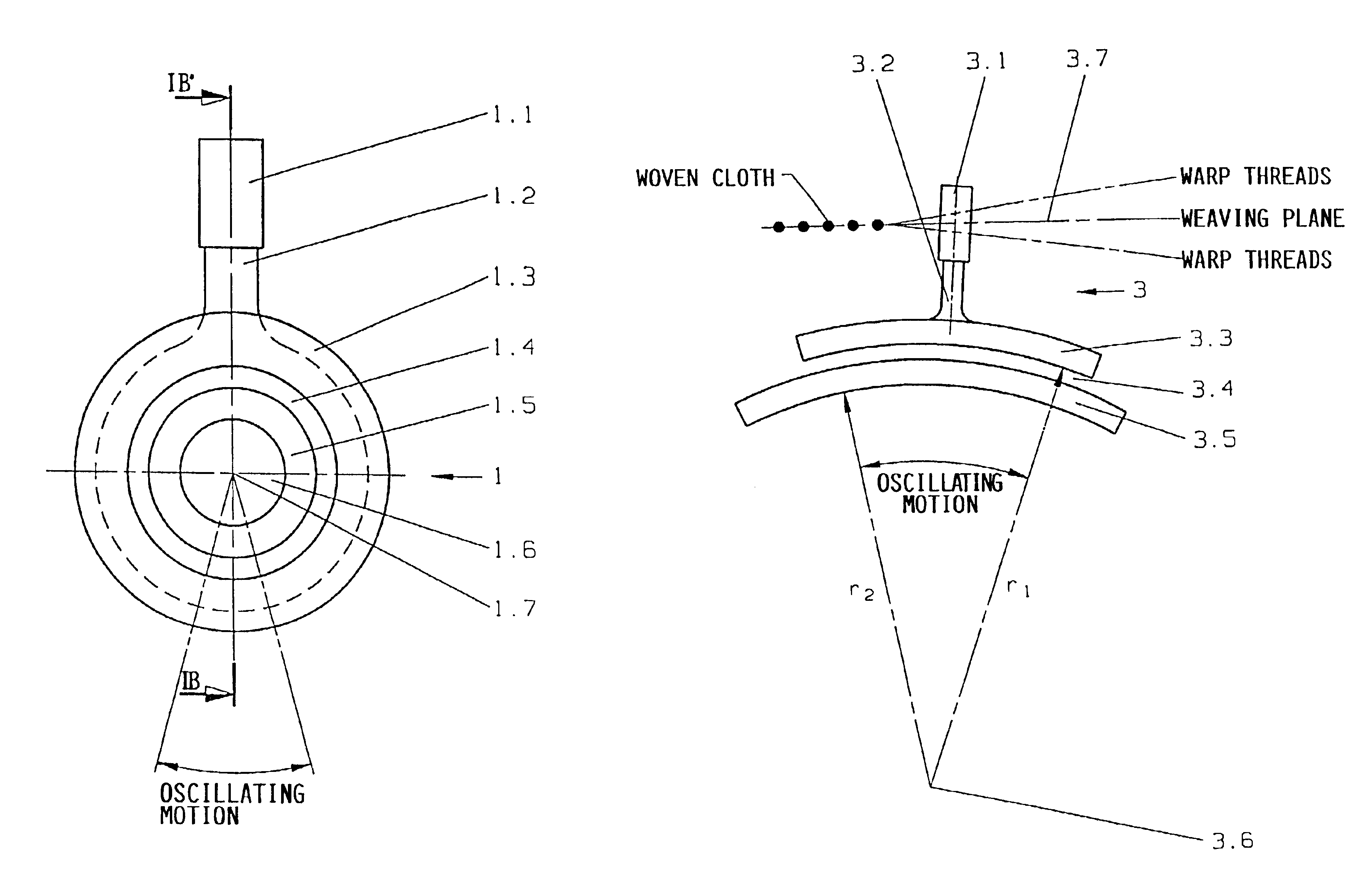
[0013]A further embodiment of the invention provides another stator or a system of stators installed in the hollow inner space of the hollow shaft forming the rotor. This inner stator or inner stator system develops a rotational moment or torque in parallel to, and in addition to, the outer stator or stator system arranged radially outwardly from the hollow shaft rotor. Thus, the inner stator system, the reed support shaft as the rotor of the direct drive, and the outer stator system are coaxially arranged relative to each other, about the oscillating pivot axis of the reed. The electric motor direct drive for the reed in this embodiment thus forms a so-called coaxial “sandwich motor” drive, which provides plural effective air gaps, whereby the total effective air gap surface of this drive is nearly doubled in comparison to the provision of a single inner rotor motor. This also leads to almost doubling the torque that can be developed.
[0015]In the second general embodiment of the invention as mentioned above, the stator and the rotor of the direct drive arrangement are configured with an arcuate shape, and particularly with a structural arrangement to avoid locating the pivoting axis of the reed within the structure of the drive, i.e. the pivot axis of the reed is located outside of its drive. This makes it possible to considerably increase the radius of the pivoting motion about the pivoting axis, and allows a relatively large air gap surface to be achieved, especially in connection with the above described sandwich motor structure. Moreover, the components that are determinative of the mass inertial moment of the weaving reed are located at the height or level of the weaving plane, i.e. above the air gap with respect to a view from the pivot axis. As a particular embodiment feature of the invention, the arc-shaped structure of the stator and of the rotor, as seen on a radial section is respectively formed as an arc segment of a circular ring or annulus. The inner and outer radii of the annular arc segments in this context are finite, i.e. <∞, which means that these arc segments have a circular arc curvature rather than being straight line segments.
[0018]This embodiment provides the following advantages. On the one hand, the available space below the weaving reed is better utilized in comparison to a coaxially constructed drive. On the other hand, the area or space above the weaving reed is additionally utilized as an installation space for the drive components. The installation space below the weaving reed can be better utilized basically due to the general advantage of the linear drive having a true straight line drive path, whereby an increase of the air gap surface merely increases the mass of the moving parts, without increasing an effective lever arm of the achieved driving force. In comparison, in a coaxially arranged drive system having a pivoting rotor, an increase of the air gap surface leads to an increase of the mass, which is further multiplied by the radius of the rotor, so that the mass inertial moment of such a coaxial drive arrangement increases more drastically than the inertial moment (associated only with the mass) of the moving part of a linear motor moving along a straight line path. Furthermore, dividing the linear drive between respective portions or areas above and below the weaving reed utilizes additional installation space as mentioned above, and also stabilizes the weaving reed motion.
[0019]The sandwich motor arrangement according to the invention can also be applied to the linear motor embodiment. Namely, the air gap surface of the linear motor can be enlarged by arranging the movable part (i.e. the rotor) and the stationary part (i.e. the stator) in plural alternating layers in a direction perpendicular to the general back-and-forth motion of the reed. In other words, assuming the typical horizontal motion of the reed, a vertical stacking of alternate rotors and stators achieves a relatively large total air gap surface with a relatively small lateral extent or dimension of the drive in the direction of motion of the reed. That is important, in order not to reduce the space available for the shed formation, e.g. the space for the motion of the heald shafts. The inventive linear drive involving a drive motion along a straight line path can be particularly embodied as a synchronous motor preferably having permanent magnets provided on the rotor, or as a transverse flux motor preferably having permanent magnets provided on the rotor. Alternatively, the linear motor can be embodied as a direct current motor or as a reluctance motor, due to the advantages already mentioned above.

