Sheet separation roller configuration

Inactive Publication Date: 2005-07-05
PANASONIC CORP
View PDF10 Cites 25 Cited by
  • Summary
  • Abstract
  • Description
  • Claims
  • Application Information

AI Technical Summary

Benefits of technology

[0028]Still further, a torque value for the retardation roller can be adjusted to be suitable to a certain specific sheet material. Thus, the prevention of overlaid sheet transfer can be implemented for various kinds of

Problems solved by technology

When the sheets are scanned for reading, the particles and dust ill-affect the image quality substantially, resulting in disturbing black lines or white-outs on a scanned image.
Such an arrangement may impair the full functioning of the anti-overlaid transfer mechanism formed with the roller 70 and the roller 80.
It is difficult for the conventional mechanism to provide an optimized anti-overlaid transfer operation; as the result, the reliability in the prevention of overlaid sheet transfer is limited.
The high μ papers are liable to cause the overlaid sheet transfer.
However, the roller 80 provided with the above-described torque an

Method used


Image

  • Sheet separation roller configuration
  • Sheet separation roller configuration
  • Sheet separation roller configuration

Examples


first embodiment

[0056]A first exemplary embodiment of the present invention is described referring to the drawings. An image scanner, which reads images out of a mother document sheet and stores them in an electronic file, is used as an example for describing the present embodiment.

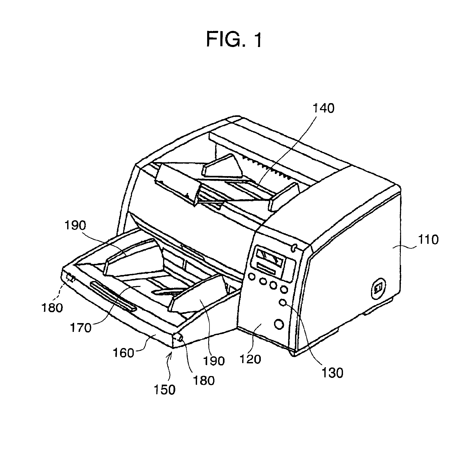
[0057]FIG. 1 is a perspective view showing a schematic structure of an image scanner equipped with a sheet feeder in accordance with the present invention. In the present example, paper is used to represent one of the sheet materials.

[0058]The image scanner is formed of a main body 110 containing an optical reading system and a sheet transfer path, and means for supplying the sheets, or an automatic sheet feeder 150. The main body 110 has an operation panel 120 in the front and a controller (not shown) inside for controlling the entire operation. Provided on the top of the main body 110 is a sheet recollection tray 140, which recollects mother document sheets supplied from the automatic sheet feeder 150 and read by the r...

second embodiment

[0082]A second exemplary embodiment of the present invention is described with reference to the drawings.

[0083]FIG. 7 shows a schematic view of a key portion of an image reader in accordance with the present invention.

[0084]In FIG. 7, a pair of guide frames 420, 430 is disposed with a certain gap in the vertical direction for guiding a document sheet supplied from a hopper (not shown) to a direction as indicated with an arrow. Along with the guide frames 420, 430, pairs of transfer rollers 440, 450 are provided. Also in the downstream of the guide frames 420, 430, pairs of transfer rollers 460, 470 are provided. A sheet is nipped by the pairs of these transfer rollers 460, 470 to be carried forward in the direction of discharge.

[0085]Provided above the guide frames 420, 430 is an optical scanning unit 480. A reading glass plate 490 is provided in the guide frame 420 crossing the beam path of the optical scanning unit 480. Light sources 500, 510 are provided in the vicinity of the re...

third embodiment

[0092]A third exemplary embodiment of the present invention is described with reference to the drawings.

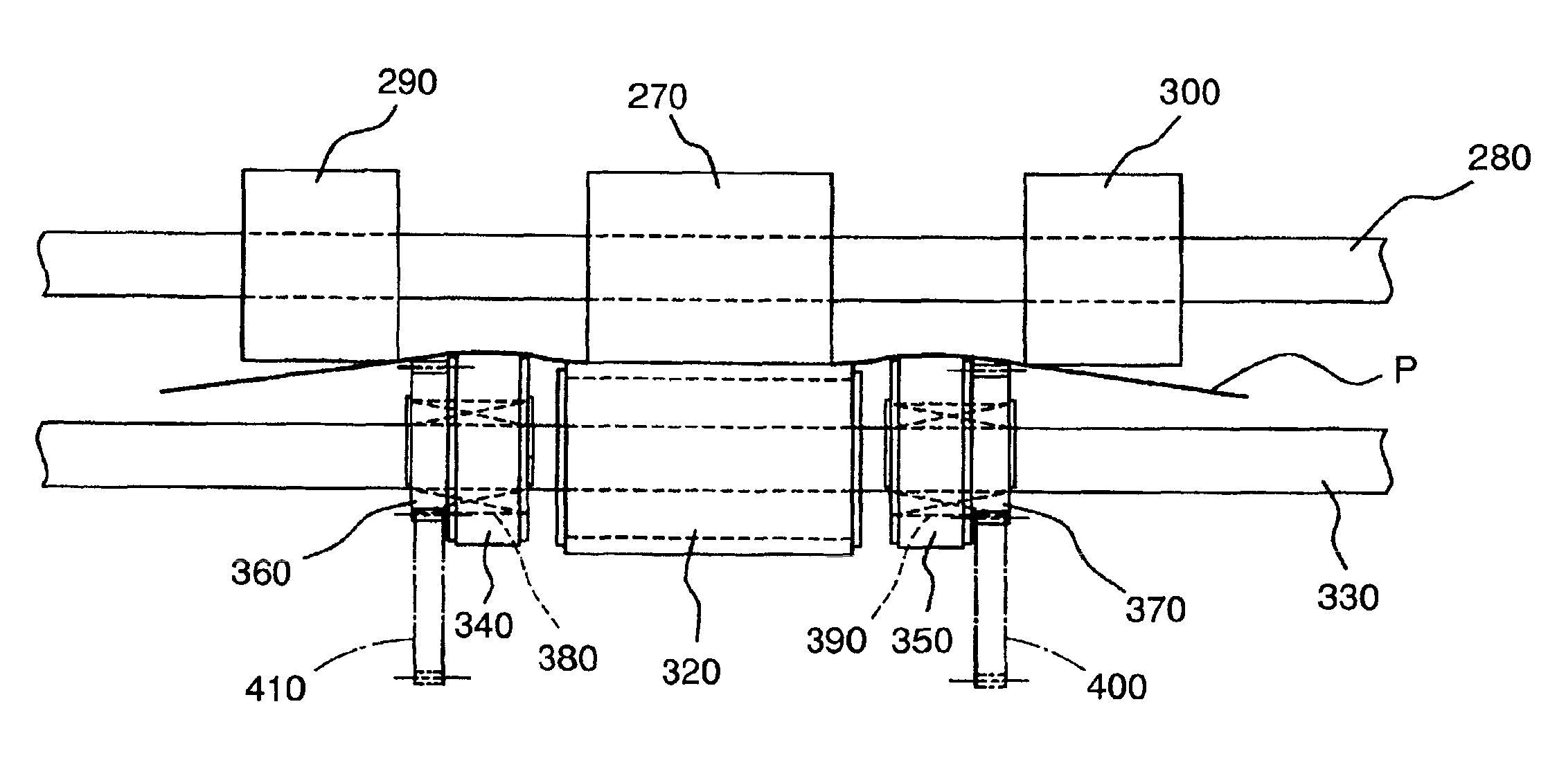
[0093]As shown in FIG. 9, a sheet feeding mechanism in the present embodiment is formed of a combination of a supply roller 600, an S roller 610 and a retardation roller 620. These rollers 600, 610 and 620 are disposed in the same arrangement as in FIG. 20, and are located above a hopper (not shown) for holding sheets P. Transfer rollers (not shown) are provided for a plurality of stages in the downstream of the roller 610 and the roller 620, which discharge the sheets P after they pass through a reading section, for example in the case of a scanner.

[0094]The roller 620 is provided with a torque limiter, which works in the following manner. Normally it revolves in a direction opposite to the sheet supply; when the roller 610 nips one sheet P it begins to revolve in the sheet supply direction. Whereas, when two or more sheets are nipped, only the uppermost sheet is sent forward and...


PUM


Abstract

An image reader comprising a reading glass plate facing an optical scanning system and a platen roller provided opposite to the reading glass plate; both being grounded. It is combined with an automatic sheet feeder, which comprises a retardation roller containing torque limiters and corrugation rollers. An optimized combination of these rollers provides an ideal sheet transfer and avoids overlaid sheet transfer. Generation of paper dust and toner particles is minimized in the optimized sheet transfer. Furthermore, sticking of such dust and particles on the reading glass plate and the platen roller is prevented in an image reader of the present invention. Thus the image reader reads out high quality images without being affected by dispersed paper dust or toner particles, while overlaid transfer of mother document sheets is prevented in the sheet feeder.

Description

FIELD OF THE INVENTION[0001]The present invention relates to an image scanner (hereinafter referred to as scanner) or the like image readers, or a copying machine or the like image forming devices. More specifically, the present invention relates to an image reader which reads images without being affected by dispersed paper dusts or toner particles at the reading section, and a sheet feeder which avoids overlaid supply of sheets.BACKGROUND OF THE INVENTION[0002]In a certain type of scanner where a mother document sheet moves to be read, the sheet sent out from a stack of sheets kept in a hopper is scanned while it passes across a reading glass plate provided in a reading line. The images on a mother document sheet are read out by an optical scanning system to be converted into electronic data.[0003]Since the sheets are transferred at a relatively high speed, paper dust and fine toner particles are readily generated therefrom and disperse, such fine dust are attracted electro-static...

Claims


Application Information

Patent Timeline
IPC IPC(8): H04N1/03H04N1/12
CPCH04N1/00909H04N1/03H04N1/0303H04N1/0305H04N1/1215
Inventor TAKAKI, KOSUKEARAKI, TAKAOSUEMATSU, JUNICHI
Owner PANASONIC CORP
Why Eureka
Try Eureka