Band coupling structure and method of manufacturing piece member therefor

a technology of coupling structure and piece member, which is applied in the direction of rod connection, horology, instruments, etc., can solve the problems of unremovable fixing, achieve the effect of preventing the coupling member from slipping out of the coupling hole and ensuring the coupling member is not slipping o

Inactive Publication Date: 2005-07-05
CITIZEN WATCH CO LTD
View PDF15 Cites 8 Cited by
  • Summary
  • Abstract
  • Description
  • Claims
  • Application Information

AI Technical Summary

Benefits of technology

[0022]With such a structure, the coupling member is also engaged with the projection formed on the outer end of the coupling hole in the piece member which is positioned on the inside in the transverse direction. Consequently, it is possible to more reliably prevent the coupling member from slipping out of the coupling hole. In addition, a spew generated by forming the coupling hole is absorbed by the formation of the projection. Therefore, the movements of the piece members in the coupling portion are not inhibited.
[0023]In this case, it is possible to provide both the projection formed on the inner end of the coupling hole in the piece member which is positioned on the outside in the transverse direction and the projection form

Problems solved by technology

In the case in which the coupling pin is used, it is pressed into the coupling hole and is thus fixed unremovably.
Furthermore, there is a possibility that the coupling

Method used


Image

  • Band coupling structure and method of manufacturing piece member therefor
  • Band coupling structure and method of manufacturing piece member therefor
  • Band coupling structure and method of manufacturing piece member therefor

Examples


example 1

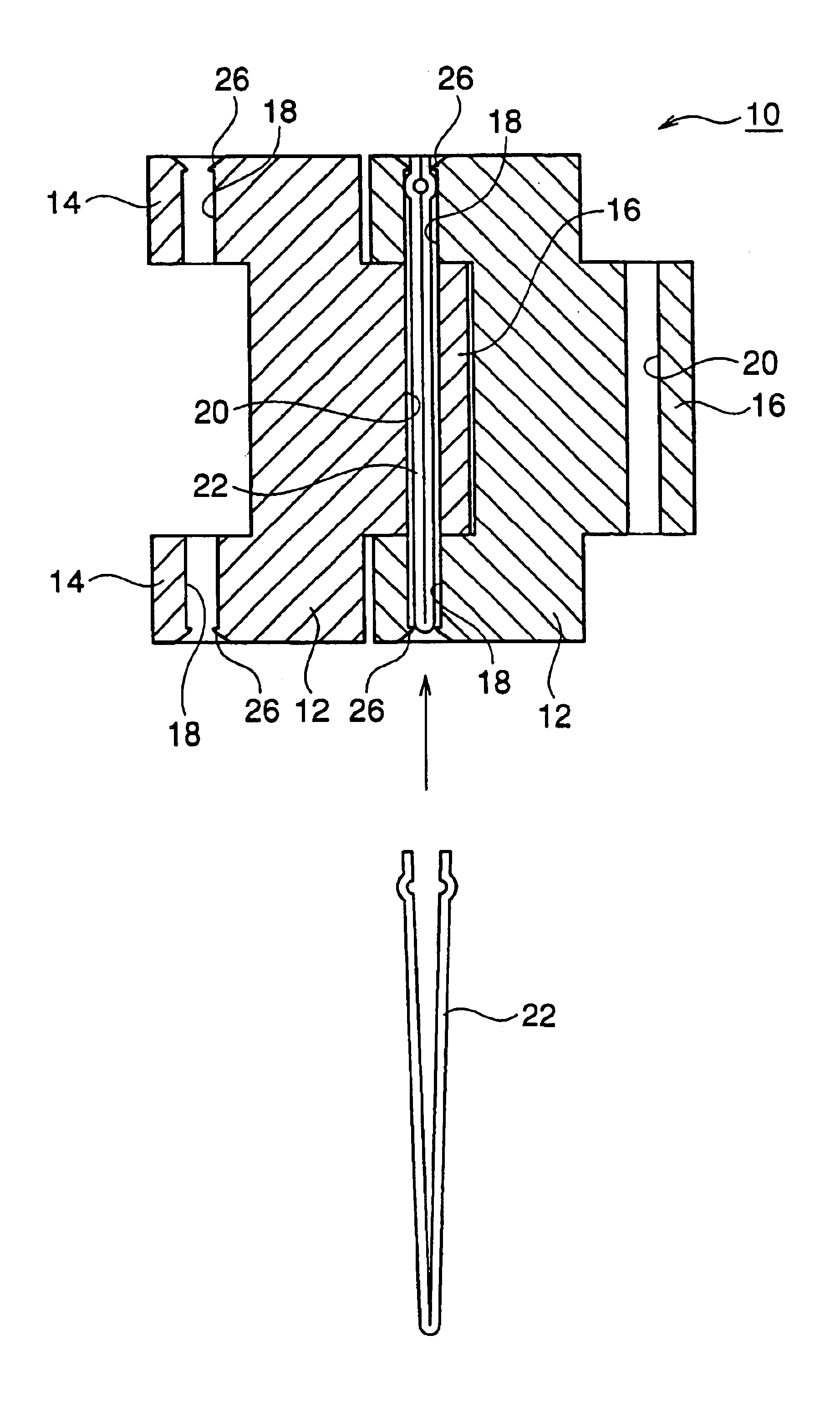
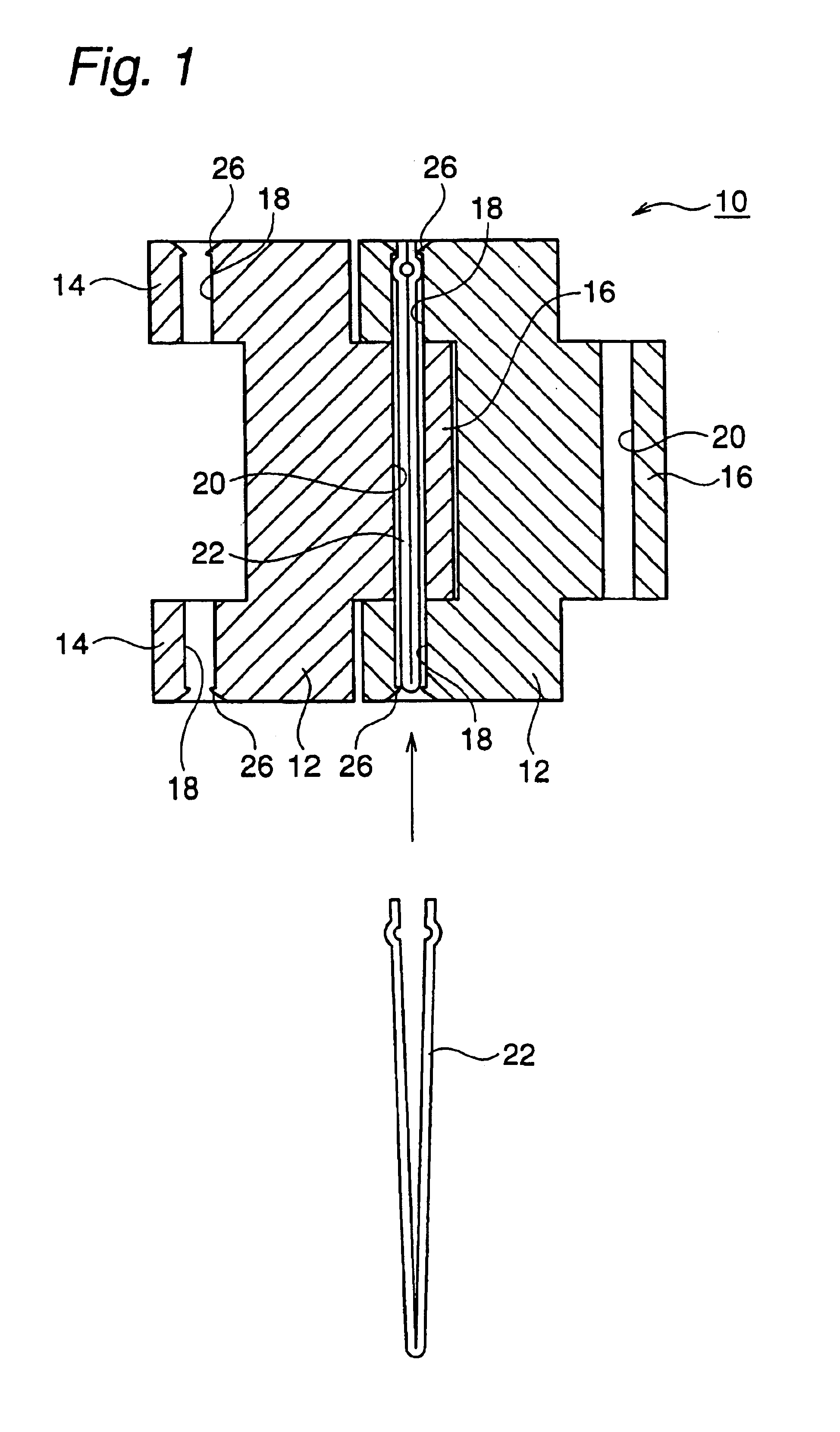
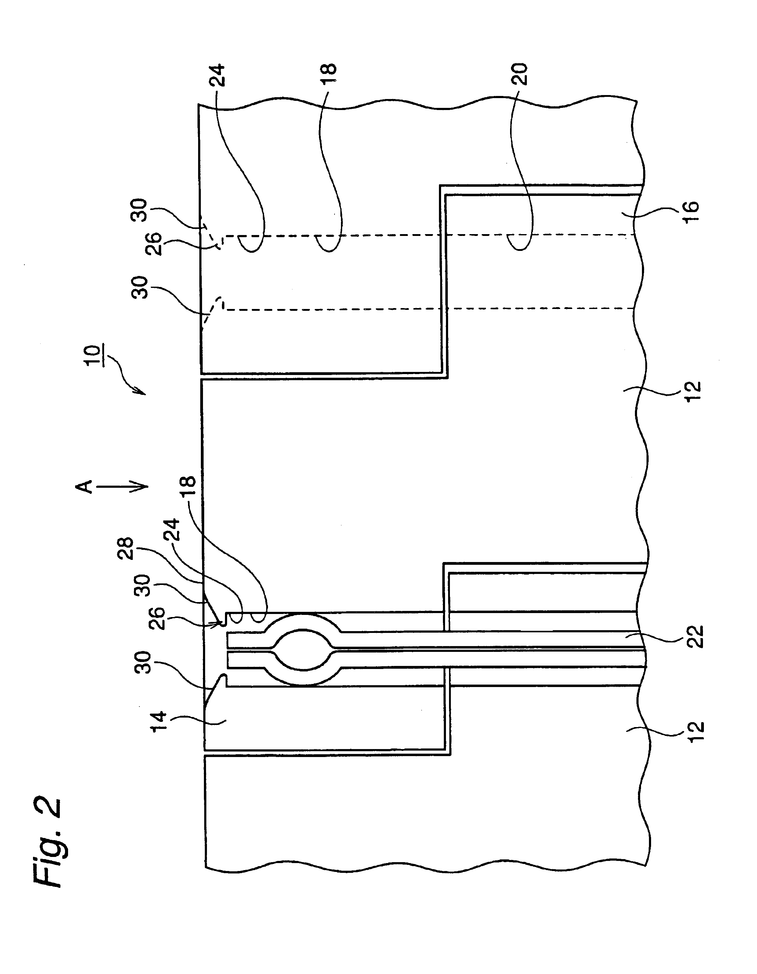
[0112]As shown in FIG. 6, the punch member 40 was pressed against the outer end of the coupling hole 18 positioned on the outside in the transverse direction of the piece member 12 by means of a punch device using a (Ti based) piece member formed of titanium (the coupling hole 18 having a diameter of 990 μmφ). As a result, the projection 26 protruded in the central direction of the coupling hole 18 from the internal wall 24 of the coupling hole 18 was formed.

[0113]The pressing was carried out by the pressing force of the punch member 40 having an impact load of 14 kgf, and the angle β formed by the slant surface 44 of the tip portion 42 of the punch member 40 was changed to 70°, 90°, 100°, 110°, 120°, 130° and 140°. Then, the hole diameter of the coupling hole 18 was measured after processing. A result is shown in the following Table 1.

[0114]As is apparent from the result of the Table 1, if the angle β formed by the cone-shaped slant surface 44 is 90° to 130°, the hole diameter is d...

example 2

[0116]In the same manner as in the example 1, the projection 26 was formed. The angle β formed by the slant surface 44 of the tip portion 42 of the punch member 40 was set to 110° and a (SUS 304 based or 316 based) piece member formed of stainless (the coupling hole 18 having a diameter of 990 μmφ) was used in place of the (Ti based) piece member (the coupling hole 18 having a diameter of 990 μmφ) formed of titanium. Moreover, the pressing force of the punch member 40 was changed to have an impact load of 4 kgf, 5 kgf, 6 kgf, 7 kgf, 8 kgf, 9 kgf, 10 kgf, 11 kgf, 12 kgf, 13 kgf, 14 kgf and 15 kgf.

[0117]The hole diameter of the coupling hole 18 after the processing and the projection distance L were measured. A result is shown in the following Table 2.

[0118]As is apparent from the result of the Table 2, the pressing was carried out by the processing force of the punch member 40 having an impact load of 5 kgf to 14 kgf. Consequently, the projection 26 was formed well, particularly at a...

example 3

[0121]A hair pin was inserted as a coupling member in the piece member and a band coupling structure was thus assembled, and the projection 26 was then formed in the same manner as in the example 1. The angle β formed by the slant surface 44 of the tip portion 42 of the punch member 40 was set to 110° and the pressing force of the punch member 40 was set to have an impact load of 8 kgf.

[0122]After the processing, antislipping force was measured. As a comparison, an antislipping force test was also executed for a band coupling structure assembled by using an unprocessed piece member. A result is shown in the following Table 3.

[0123]As is apparent from the result of the Table 3, the piece member fabricated according to the present invention had considerably great antislipping force and a more excellent effect of preventing the coupling member from slipping off as compared with the conventional unprocessed piece member.

[0124]

TABLE 3Antislipping force mean value (kg / cm2)βPrior artInvent...


PUM

PropertyMeasurementUnit
Forceaaaaaaaaaa
Forceaaaaaaaaaa
Forceaaaaaaaaaa

Abstract

A coupling structure of a watch band in which a coupling member such as a coupling pin or a hair pin does not sup from a coupling hole even if a user practices strenuous sports or a rotation and a twist are always applied to the coupling portion due to use for years, and a method of manufacturing a piece member for the band coupling structure. In a coupling structure of a band comprising a plurality of piece members, a projection protruded in a central direction of a coupling hole from an internal wall of the coupling hole is formed on an outer end of the coupling hole in the piece member positioned on an outside in a transverse direction, and a coupling member is inserted in the coupling hole provided in the transverse direction of the piece member and is engaged with the projection, thereby coupling the piece members to each other.

Description

BACKGROUND OF THE INVENTION[0001]1. Field of the Invention[0002]The present invention relates to a coupling structure of a band comprising a plurality of piece members such as a band of a wrist watch and to a method of manufacturing the piece member for the coupling structure.[0003]2. Description of the Prior Art[0004]A conventional watch band structure comprises a plurality of piece members that are coupled to each other in a longitudinal direction which can be bent freely in conformity with the shape of a user's arm (see Japanese Laid-Open Utility Model Publications Nos. Sho 50(1975)-50071 and Sho 51(1976)-121368).[0005]In a coupling structure 100 of a watch band, for example, depicted in FIGS. 15 and 16, coupling holes 108 and 110 are formed on coupling ends 104 and 104 on the outside in a transverse direction which are formed on one of the ends of an almost U-shaped piece member 102 and a coupling projection 106 in a central part which is formed on the other end respectively. Th...

Claims


Application Information

Patent Timeline
IPC IPC(8): A44C5/00A44C5/10
CPCA44C5/105Y10T403/55Y10T403/49Y10T403/32893Y10T403/553A44C5/10
Inventor YAMAKAWA, JINDAISANO, MAMORUTAGUCHI, HIDEO
Owner CITIZEN WATCH CO LTD
Why Eureka
Try Eureka