Apparatus for the treatment of metallic workpieces with cooling gas

a technology for cooling gas and apparatus, which is applied in the direction of mechanical apparatus, liquid fuel engines, quenching agents, etc., can solve the problems that the recharging of the furnace is only ever possible, and achieve the effects of rapid flow reversal, compact construction, and low chamber volume ratio

Inactive Publication Date: 2005-07-05
ALD VACUUM TECH GMBH
View PDF5 Cites 11 Cited by
  • Summary
  • Abstract
  • Description
  • Claims
  • Application Information

AI Technical Summary

Benefits of technology

[0005]The most fundamental disadvantage of all known vacuum furnaces, however, is that renewed charging of the furnaces is only ever possible after total completion of the previous treatment process in each case, and this means, where large-scale manufacture is required, setting up a large number of complete vacuum furnaces. Since, however, the first phase of the heat-treatment process, namely the heating-up and carburising of the batch, takes a relatively long time compared with the second phase, namely the hardening process, the object on which the present invention is based is to provide an apparatus for the treatment of metallic workpieces with cooling gas which avoids the disadvantages of known furnaces and with a very compact construction—with a low ratio of chamber volume to batch volume—enables a rapid flow reversal, and in which mirror-symmetrical flow conditions exist after the flow reversal. Furthermore, the apparatus is to be of single-walled design and, from the very beginning of the quenching phase, enable a high heat transfer coefficient at all the workpieces within the batch, is to require a small amount of quenching gas per quenching operation and permit operation with particularly short cycle times. Finally, the apparatus is to be designed so as to enable controlled quenching—i.e. with variable intensity—and to be capable of being coupled to existing carburising furnaces, so that a plurality of simple furnaces—without heat exchanger and cooling-gas blower—can be operated with a single apparatus, which reduces costs and saves space.

Problems solved by technology

The most fundamental disadvantage of all known vacuum furnaces, however, is that renewed charging of the furnaces is only ever possible after total completion of the previous treatment process in each case, and this means, where large-scale manufacture is required, setting up a large number of complete vacuum furnaces.

Method used


Image

  • Apparatus for the treatment of metallic workpieces with cooling gas
  • Apparatus for the treatment of metallic workpieces with cooling gas

Examples


Embodiment Construction

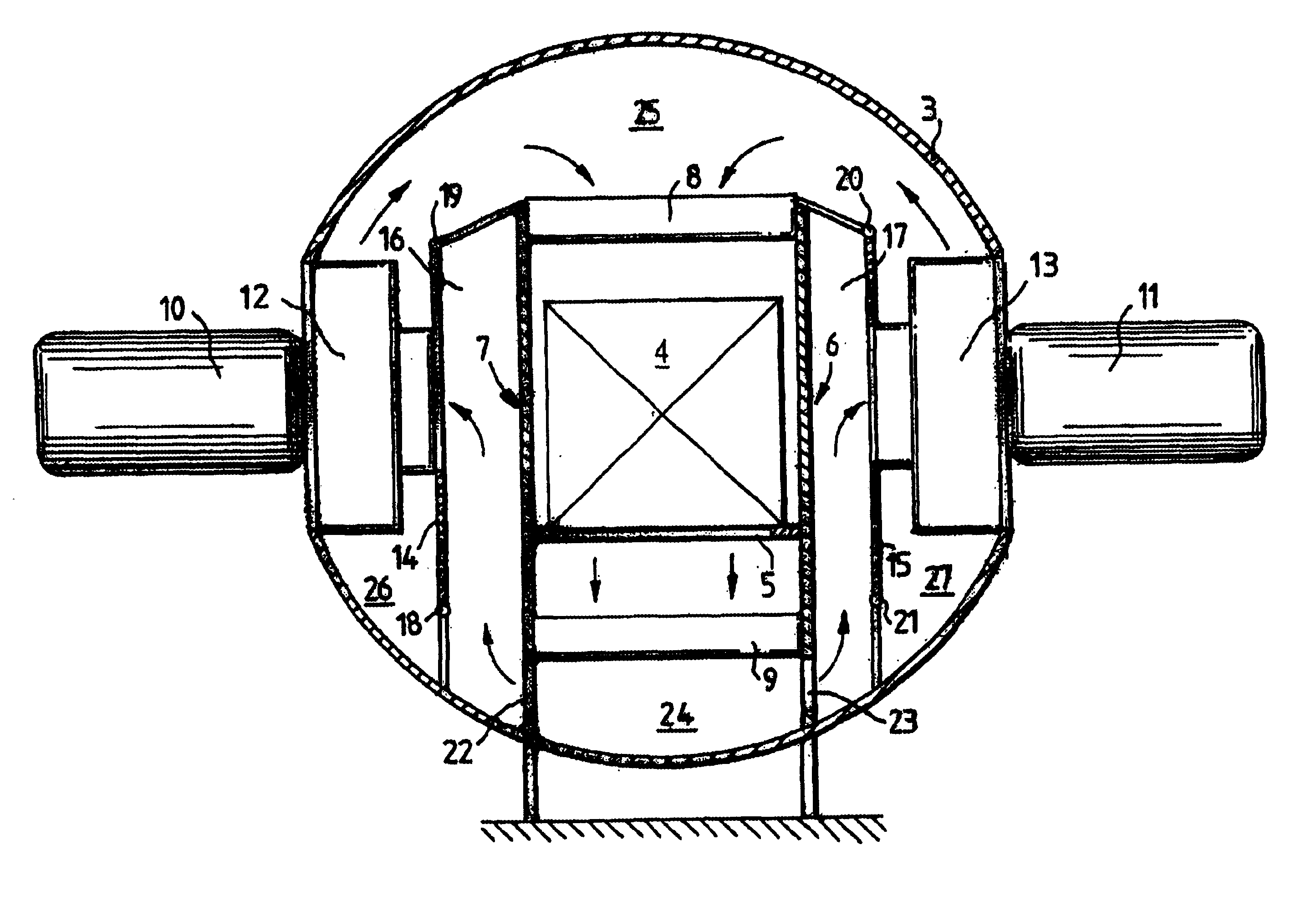
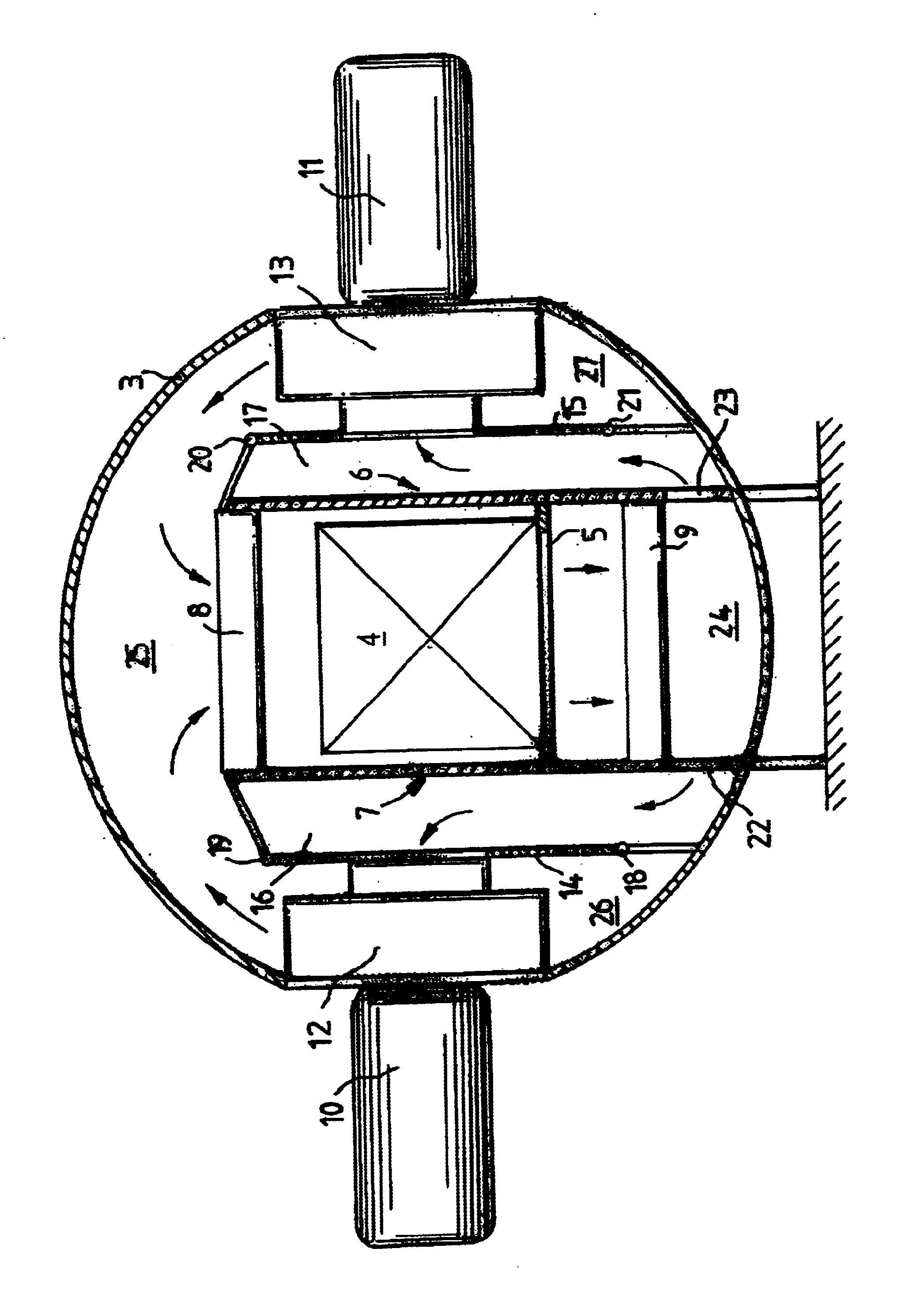
[0010]The apparatus comprises a cylindrical, single-walled housing 3, one end of which is firmly closed by a cover and the other end of which can be closed by means of a door or a slide and otherwise is configured and dimensioned in such a way that the workpiece batch 4, which has been heated up and carburised in a separate furnace, can be transferred into the housing 3 of the apparatus without additional transporting equipment being required for this purpose. Arranged in the housing 3 is a workpiece support 5 in the form of a perforated or apertured plate, on which the batch 4 rests. Arranged on both sides of the batch 4 are strongly designed support plates 6, 7, on which the workpiece support 5 is held and between which heat exchangers 8, 9 are located. Provided on both sides of the housing 3, on the outer side of the latter, are blower motors 10, 11, the motor shafts of which are sealingly led through the wall of the housing 3, the two motor shafts extending in mutual alignment a...


PUM

PropertyMeasurementUnit
temperatureaaaaaaaaaa
metallicaaaaaaaaaa

Abstract

In an apparatus for the treatment of metallic workpieces (4) with cooling gas, having a cylindrical housing (3) with an opening at the end face for introducing and removing the workpieces (4), two support plates (6, 7) extending in parallel planes vertically in the housing (3) and two air-guiding plates (14, 15) are provided, the workpiece batch (4) being held between the support plates (6, 7), and the air-guiding plates (14, 15) each forming, with the adjacent support plates (6, 7) and with the respectively adjacent inner wall of the housing, shafts (16, 17 and 26, 27, respectively) through which the cooling gas conveyed by blowers held on the housing (3) flows, controlled by reversing flaps (18, 19, 20, 21) arranged at the upper and lower ends of the air-guiding plates (14, 15).

Description

FIELD OF THE INVENTION[0001]The invention relates to an apparatus for the treatment of metallic workpieces with cooling gas, having a housing with an opening for introducing and removing the workpieces, having a cooling-gas source, by means of which blower-conveyed cooling gas guided via heat exchangers is fed to the workpieces, and having a workpiece support.BACKGROUND AND SUMMARY OF THE INVENTION[0002]Vacuum furnaces for the plasma carburisation of metallic workpieces by means of a carbon-containing gas, for example methane or propane, are known. During the plasma carburisation, the workpieces are heated in the vacuum furnace to a temperature of between about 800° C. and 1050° C. Subsequently, the carbon-containing process gas is led into the furnace chamber and an electric field is applied to the workpiece batch. Thereafter, for the purpose of hardening, the batch is cooled by blowing it with cooling gas emerging from nozzles onto the batch, helium, in particular, having proved s...

Claims


Application Information

Patent Timeline
Patent Type & Authority Patents(United States)
IPC IPC(8): C21D1/74C21D1/767C21D1/773C21D1/613C21D1/56
CPCC21D1/613C21D1/767C21D1/773
Inventor LOESER, KLAUSSTUEBER, GEORGWELZIG, GERHARDHEUER, VOLKER
Owner ALD VACUUM TECH GMBH
Why Eureka
Try Eureka