Method and apparatus for the overlapping welding of sheet-like plastic materials

a technology of plastic materials and welding equipment, applied in the direction of processing materials, packaging, lamination, etc., can solve the problems of affecting the welding seam, affecting the welding process, so as to achieve a better and more crease-free weld seam, small punctiform unevenness, and sufficient fusion

Inactive Publication Date: 2005-07-05
LEISTER TECHNOLOGIES
View PDF15 Cites 12 Cited by
  • Summary
  • Abstract
  • Description
  • Claims
  • Application Information

AI Technical Summary

Benefits of technology

[0007]Thus, in the method according to the invention, it is no longer necessary to lift both material webs. By the upper material web being lifted essentially only to an extent such that the heating wedge can pass between the material webs, the lifting height is substantially lower than in the method and apparatuses employed hitherto. Consequently, a substantially better and more crease-free weld seam can be produced. Owing to the low height, there is no longer the risk of the distortion of the material webs. Surprisingly, with this method, it is possible, by the heating wedge being moved over the lower material web, to achieve sufficient fusion even here and thereafter to make a firm connection of the two material webs.
[0008]It is possible, in principle, that the sheet-like firm base either is not completely planar, but rather has different surface level heights, or, despite every care, has on it small punctiform unevennesses. In order precisely to avoid this, the methods known from the prior art have been used and corresponding welding appliances employed. According to a preferred embodiment of the method, therefore, during movement over the lower material web, the heating wedge, in the event of unevennesses, is moved under the latter in the vertical direction without loss of contact. By virtue of a floating mounting, slight unevennesses of this kind below the lower material web can be compensated by the heating wedge. In addition to this, the heating wedge is pressed onto the lower material web via a resiliently mounted holding-down roller which presses the upper material web against top sides of the heating wedge. This ensures that both material webs are sufficiently contacted by the heating wedge and consequently heated and at the same time can react automatically to variations in the base.
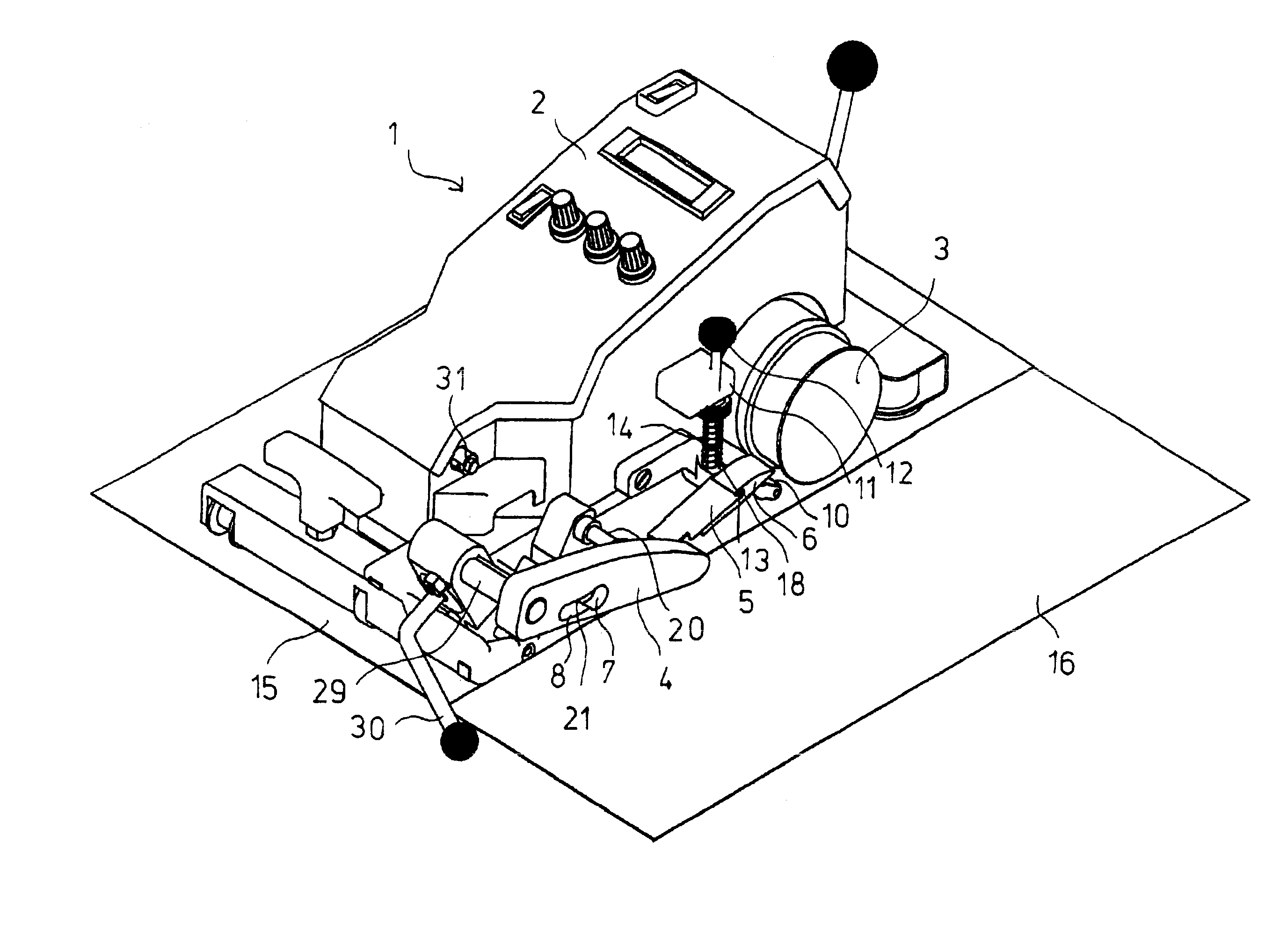
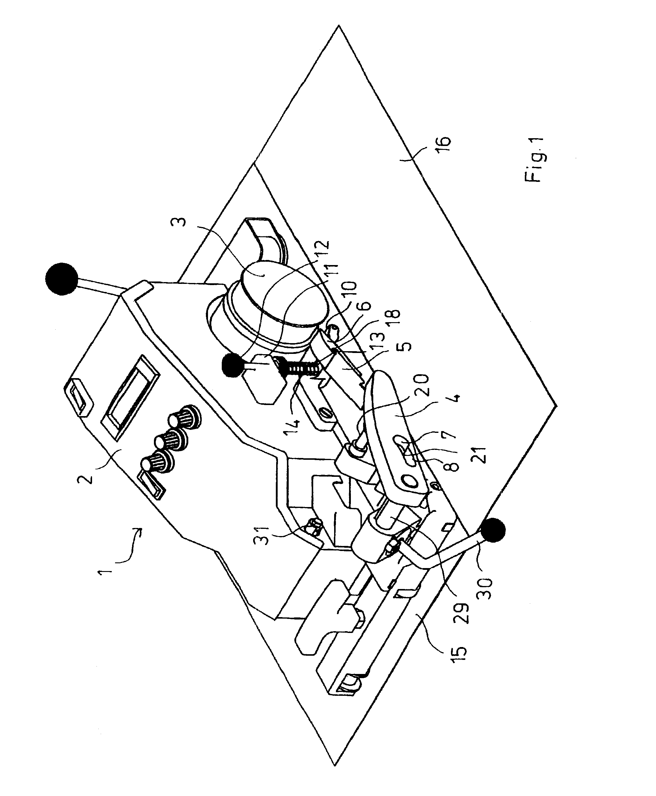
[0013]The welding appliance according to the invention comprises a device for carrying and moving the heating device in the form of a heating wedge from a standby position remote from the pressure roller to a welding position located near to the pressure roller and on the lower material web and a device for pressing the heating wedge resiliently onto the lower material web in the welding position. The device for carrying and moving the heating wedge may in this case, depending on the design of the carriage, consist of various structures making it possible to bring the heating wedge out of the standby position into the welding position. The device for pressing the heating wedge resiliently may press the heating wedge onto the lower material web directly or indirectly via the upper material web.
[0015]According to a preferred embodiment of the welding appliance, the device for carrying and moving the heating wedge has a holding arm, at the front end of which the heating wedge is arranged. According to a further advantageous refinement, this holding arm is provided with a guide slot, into which a guide pin engages. The guide slot issues into a guide orifice with guide edges, so that the guide pin, when it penetrates into the guide orifice, induces a movement of the holding arm transversely to the longitudinal direction of the heating wedge. Correspondingly designed guide edges in the guide orifice bring about the desired movement of the guide wedge mounted at the end of the holding arm into various positions.
[0017]According to a particularly preferred refinement of the invention, the device for pressing the heating wedge resiliently onto the lower material web comprises a pressure device for pressing the upper material web onto the heating wedge. In this case, the pressure device is preferably designed as a holding-down roller which is resiliently adjustable in the vertical direction and which at the same time also presses the heating wedge against the lower material web via the upper material web. Bearing elements for the heating wedge allow a restricted movement of the heating wedge in the vertical direction, so that it can thereby react to unevennesses below the lower material web. The movements of the heating wedge in the vertical direction thus allow a lowering or raising of the heating wedge or the tip or a lateral tilting.
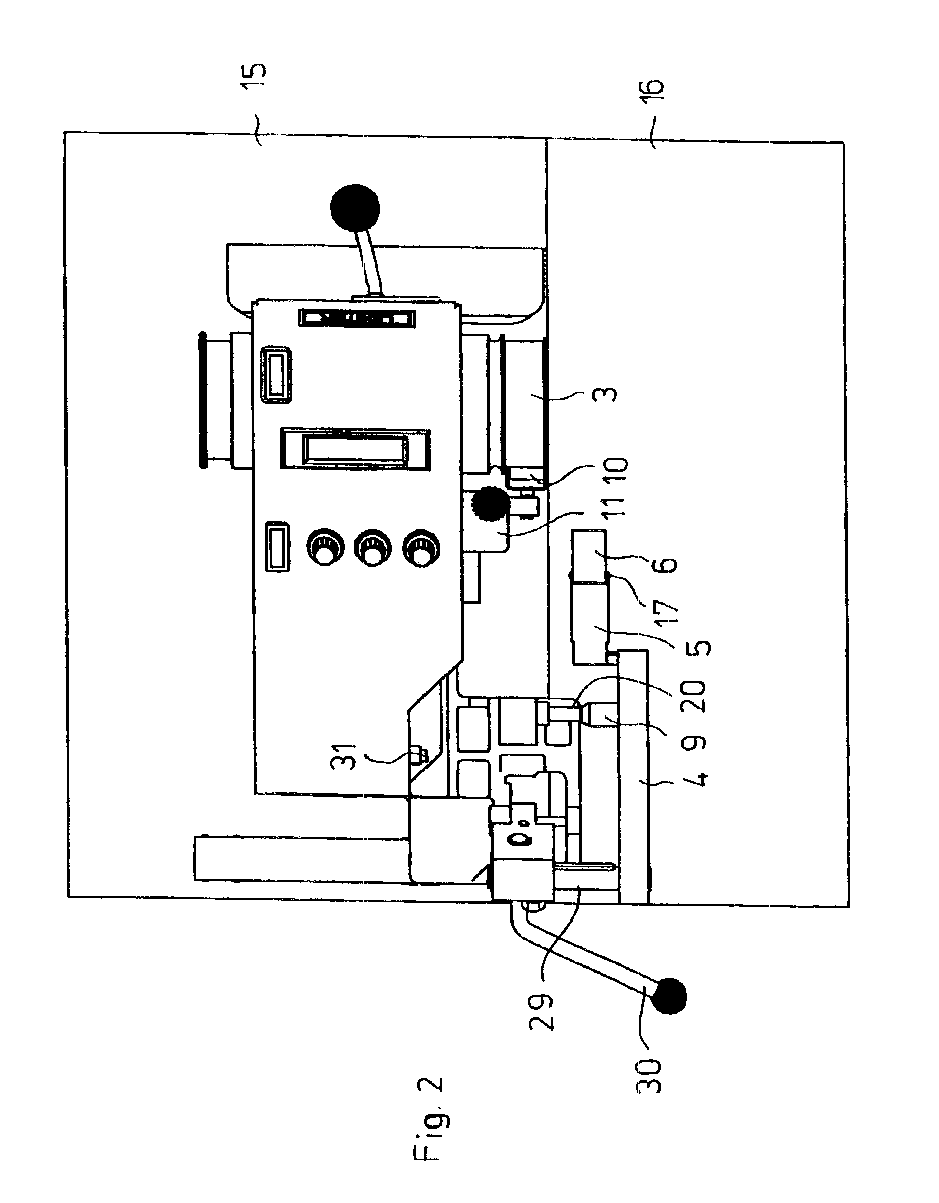
[0019]According to a further advantageous refinement, the heating appliance has a guide device which presses onto a rail lying on the material webs. This guide device and the associated rail may, of course, be used not only in the case of a welding appliance with a heating wedge, but also in the case of a welding appliance with a hot-air device and welding nozzle. The rail, for example with a maximum length of 2 m, may in this case be designed in such a way that, by two rails of this type being lined up with one another, a continuous run of the welding appliance along the material webs is possible. By the weight of the welding appliance, the rail is pressed onto the material webs precisely in the region in which the heating wedge is located, so that distortion or creasing is not readily possible here. Preferably, therefore, the guide device is arranged on that side of the carriage which is located opposite the heating device and has suitable rollers which press onto the rail.

Problems solved by technology

This method and the welding appliances used for the purpose have the disadvantages that, by the material webs being lifted, on the one hand, they may form creases which impair the weld seam, and, furthermore, there is the risk of distortion of the material webs.
Furthermore, the handling of the welding appliance is made more difficult by the sometimes relatively thick and rigid material webs when these material webs are being lifted.

Method used


Image

  • Method and apparatus for the overlapping welding of sheet-like plastic materials
  • Method and apparatus for the overlapping welding of sheet-like plastic materials
  • Method and apparatus for the overlapping welding of sheet-like plastic materials

Examples


Embodiment Construction

[0035]FIG. 1 illustrates the welding appliance 1 with the housing 2 and with the pressure roller 3 which is at the same time also a drive roller. The basic construction of welding appliances of this type is generally known and is not described in any more detail below. Arranged on the housing 2 is a holding arm 4 which at one end carries the heating wedge 6 via a holding plate 5. The heating wedge 6 is electrically heated in the usual way and, for this purpose, contains the necessary feeders and devices which are known to a person skilled in the art and are therefore not discussed in any more detail. The heating wedge 6 (FIG. 12) is mounted in elongate vertical lugs 18 of the holding plate 5 via pins 17, so that controlled movements in the vertical direction as a result of unevennesses can be executed. The heating wedge 6 has a curved upper heating contact surface 22 and a lower planar heating contact surface 23. The latter is longer than the upper heating contact surface 22.

[0036]F...


PUM

PropertyMeasurementUnit
lengthaaaaaaaaaa
plasticaaaaaaaaaa
pressureaaaaaaaaaa

Abstract

A method for the welding of plastic materials in the form of webs, films or the like by means of a heating wedge, welding being carried out without the use of a second pressure roller below the welded material webs. For this purpose, the heating wedge is placed onto the lower material web and is moved over the latter under pressure. The pressure is generated via a holding-down device which has a holding-down roller and which presses onto the upper material web and onto the heating wedge. A floating mounting for the heating wedge compensates for slight unevennesses on the lower material web.

Description

BACKGROUND OF THE INVENTION[0001]The present invention relates to a method for the overlapping welding of sheet-like plastic materials by means of a heating wedge which is moved between the upper and the lower web and heats the materials, the material webs, after heating and fusing, being combined and being pressed together. The invention relates, moreover, to a welding appliance for the overlapping welding of sheet-like plastic materials, with a carriage carried and driven by rollers, at least one of the rollers being designed as a pressure roller for pressing together the materials brought, hot, into contact with one another, and a heating device which can be introduced between the material webs and which, during contacting, fuses the material webs on the sides facing one another, and to the use of a guide rail for welding appliances of this type.[0002]For the welding of sheetings consisting of coated fabric, films and sealing webs made from PVC-P, PE, ECB, CSPE, EPDM, PVDF etc. a...

Claims


Application Information

Patent Timeline
Patent Type & Authority Patents(United States)
IPC IPC(8): B29C65/20B29C65/18B29C65/78B29C65/10B29C65/24B29L7/00
CPCB29C66/1122B29C66/43B29C66/80B29C66/8362B29C66/86533B29C65/2061B29C65/10B29C65/7835B29C65/7894Y10T156/1788Y10T156/1715B29C65/00B29C66/71B29C66/8161B29C66/8221B29C66/8223B29K2023/06B29K2023/16B29K2027/06B29K2027/16B29C65/20B29C65/18
Inventor ZURMUEHLE, WALTERZIMMERLI, PAUL
Owner LEISTER TECHNOLOGIES
Why Eureka
Try Eureka