Multi-mode renewable power converter system

a technology of renewable power and converter system, which is applied in the direction of electric vehicles, electric generators, transportation and packaging, etc., can solve the problems of high cost of solar energy conversion in general, unresolved environmental problems such as nuclear waste and carbon dioxide emission from thermal power plants, and inability to convert solar energy in general. high efficiency and other issues

Inactive Publication Date: 2005-07-05
PHOENIXTEC POWER
View PDF3 Cites 368 Cited by
  • Summary
  • Abstract
  • Description
  • Claims
  • Application Information

AI Technical Summary

Benefits of technology

[0009]The main object of the present invention is to provide a multi-mode renewable power converter system that is able to convert DC power from PV array to AC to suit the different power requirements for both standalone load and grid-connected systems.

Problems solved by technology

Environmental issues such as nuclear waste and carbon dioxide emission from the thermal power plant are still unresolved up to the present.
However, conversion of solar energy in general is still very expensive, and the efficiency of inverters for converting DC output from solar cells to sinusoidal AC power is another challenge for producers of power generators. FIG. 7 shows the architecture of a conventional solar power generator, solar power collected by a solar panel is converted to AC power by an inverter.
Generally, for certain heavy duty applications, the voltage of the storage battery is not high enough, it needs additional conversion stages to boost the output voltage, but in that case, the total power conversion efficiency from renewable power source to AC output will not be very high (approx.
Although this can make the maximum use of PV array, the conversion efficiency cannot be improved.
The shortcoming of such system is that it lacks a back-up power system.
Even if a battery can be connected to the system output, the voltage is too high for ordinary user applications.
An additional charger must be used resulting in increased circuit complexity and inconvenience to ordinary power users.

Method used


Image

  • Multi-mode renewable power converter system
  • Multi-mode renewable power converter system
  • Multi-mode renewable power converter system

Examples


Embodiment Construction

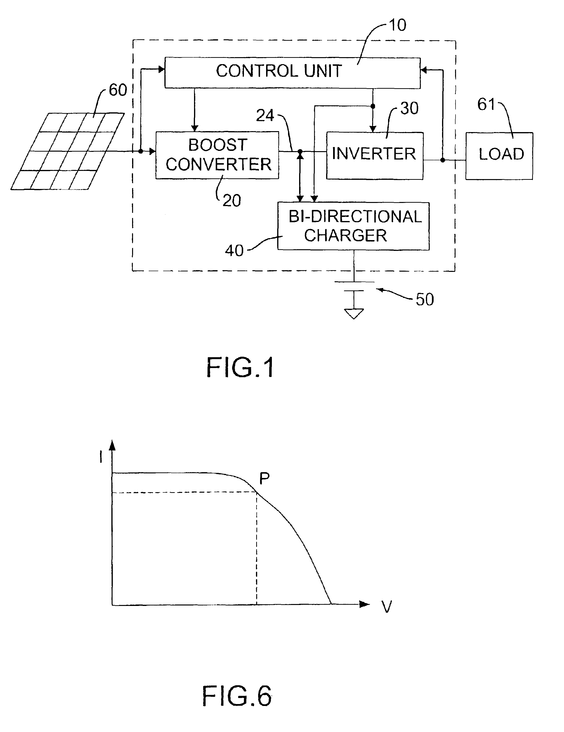
[0024]The present invention provides a multi-mode renewable power converter system, which is able to operate in different modes to suit various power and load requirements, maintaining high power conversion efficiency and ease of operation.

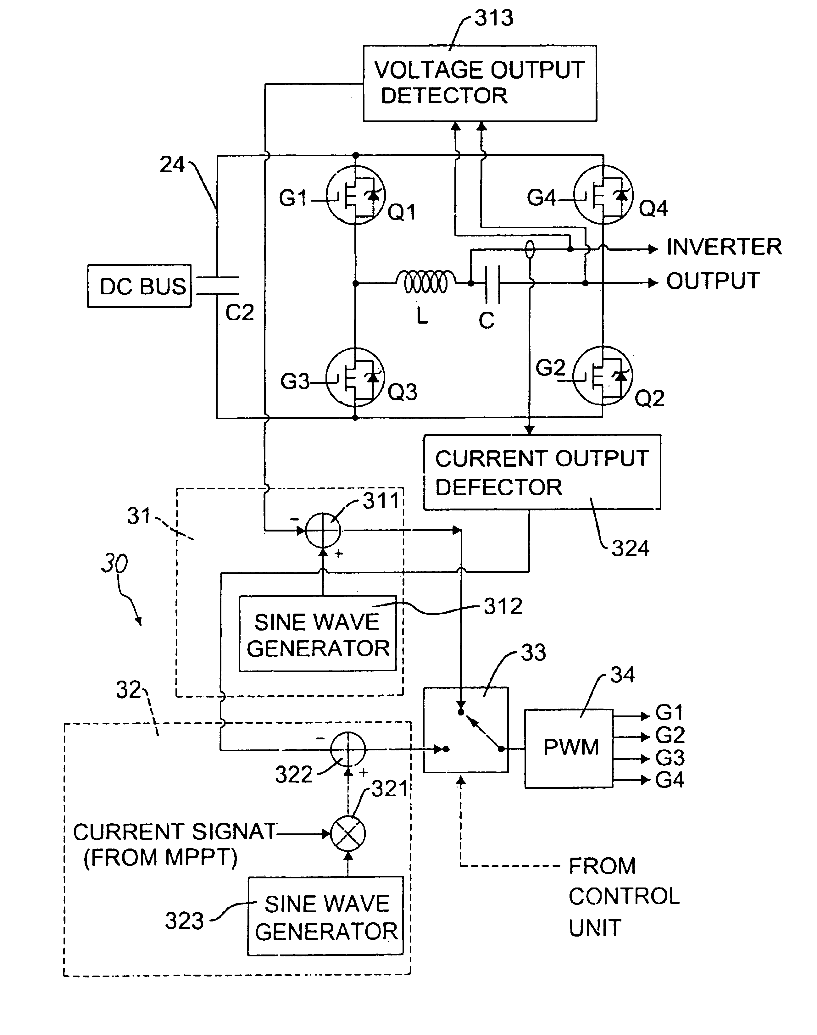
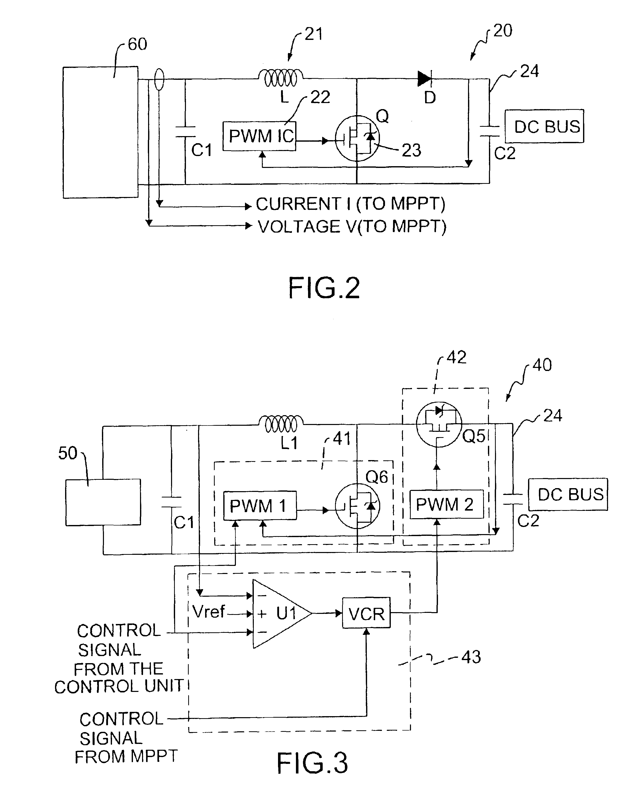
[0025]As shown in FIG. 1, the architecture of the renewable power converter system includes a control unit (10), a boast converter (20), an inverter (30) and an optional bi-directional charger (40). The bi-directional charger (40) is connected to a storage battery (50), and the boost converter (20) is connected to the DC output of a renewable power source (60).

[0026]The control unit (10) has incorporated an MPPT function for tracking and controlling the power output so as to enable the optimal usage of the power from the renewable power source (60) to the inverter (30) and then on to the power user. The control unit (10) can be established by firmware in a microprocessor or by a hardware implementation, wherein the function of the MPPT can also be...


PUM

PropertyMeasurementUnit
voltageaaaaaaaaaa
currentaaaaaaaaaa
resistance valueaaaaaaaaaa

Abstract

A multi-mode renewable power converter system is disclosed. The system includes a control unit, a boost converter, an inverter and optional bi-directional charger, wherein the boost converter converts DC output of a solar cell or a renewable source to high DC bus voltage, and the inverter converts this DC bus voltage to an AC output. This power converter can be used to support standalone load or grid-connected system with a dynamic maximum power point tracking (MPPT) circuit. The MPPT circuit detects the current and voltage from the solar cell and indicates to the inverter to provide power to the load connected. When the optional bi-directional charger is installed, the MPPT signal is also fed to this charger to make the power efficiency maximized for the system.

Description

BACKGROUND OF THE INVENTION[0001]1. Field of the Invention[0002]The present invention relates to a multi-mode renewable power converter system, in particular to a power converter that is able to operate with different modes to suit various power and load requirements. In addition, it can also improve conversion efficiency in some existing solar power conversion systems.[0003]2. Description of Related Arts[0004]The electrical power demand from industrial and household users continue to increase, amidst growing concerns of the pollution problems and the depletion of coal and oil in our planet. The technology for utilizing renewable power from the natural resources has received increasing attention by scientists around the world. Among all the alternatives, solar power appears to be most promising, because it is most abundant in our environment and the cleanest among all. People living in remote areas and satellite towns have been using solar cells to supplement their regular power sup...

Claims


Application Information

Patent Timeline
Patent Type & Authority Patents(United States)
IPC IPC(8): H02J7/35
CPCH02J7/35Y02E10/58Y02E10/56
Inventor SUNG, CHANG-CHE
Owner PHOENIXTEC POWER
Why Eureka
Try Eureka