Liquid crystal display device, method for producing the liquid crystal display device, and electronic apparatus

a liquid crystal display and liquid crystal technology, applied in the direction of instruments, polarising elements, optics, etc., can solve the problem of insufficient luminance in the transmission mode, and achieve the effect of good polarization properties, excellent visibility, and good polarization properties

Inactive Publication Date: 2005-07-05
BOE TECH GRP CO LTD
View PDF8 Cites 3 Cited by
  • Summary
  • Abstract
  • Description
  • Claims
  • Application Information

AI Technical Summary

Benefits of technology

[0015]Accordingly, in the liquid crystal display device shown in FIG. 8 having the polarizing layer 121 disposed at the inner sides of the substrates 101 and 102, the light incident upon the polarizer 119 from the liquid crystal layer 104 is linearly polarized light when a bright display is provided in the transmission mode. Therefore, there is almost no light absorbed by the polarizer 119. Consequently, the liquid crystal display device makes it possible to address or overcome the problem of the luminance being insufficient in the transmission mode, which is a problem in related art transflective liquid crystal display devices, and can provide a bright display.
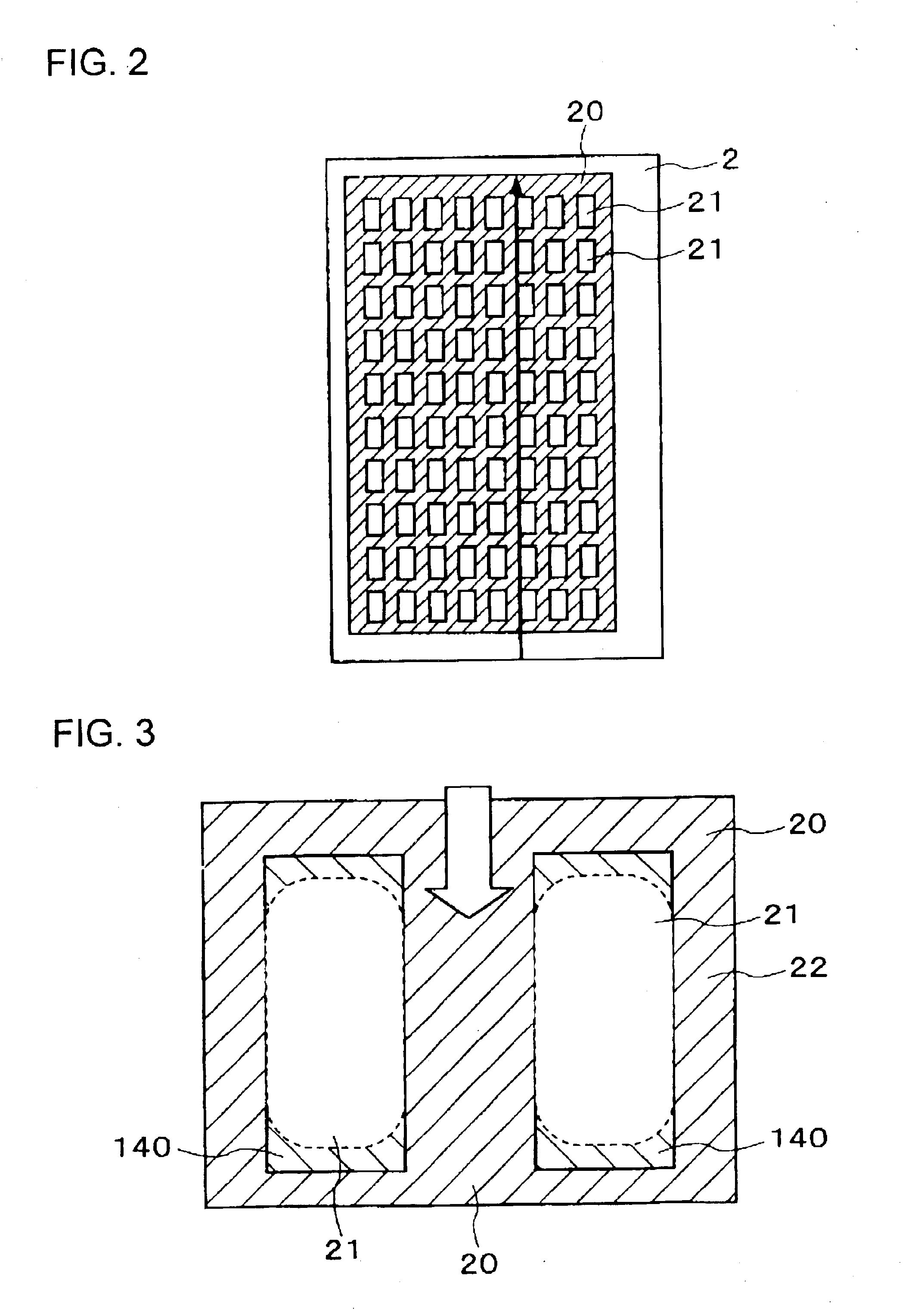
[0020]The inner polarizing layer produced by the method of the present invention is such that the direction in which stress is exerted during the application thereof is substantially the same as the direction of extension of the opening defined by a step formed by the opening and the reflective layer, so that the fraction of a portion at the step that extends in a direction intersecting the direction in which the stress is exerted is reduced, so that nonalignment in the material of the inner polarizing layer can be reduced or minimized. This makes it less likely for a reduction in the property of the inner polarizing layer caused by the non-alignment to occur, so that a light source can be used with higher efficiency. Therefore, a liquid crystal display device that provides a bright transmissive display can be provided.
[0022]According to this method of the present invention, in forming an inner polarizing layer, an alignment layer for the inner polarizing layer aligned in the same direction as the direction of extension of the opening of the reflective layer is first formed. Then, the inner polarizing layer is formed on the alignment layer for the polarizing layer. Therefore, by interposing the alignment layer for the inner polarizing layer between the reflective layer and the inner polarizing layer, the degree of non-alignment in a portion of the inner polarizing layer at the opening of the reflective layer can be reduced. In addition, since the alignment layer for the polarizing layer is aligned in the same direction as the direction of extension of the opening of the reflective layer, alignment properties at the boundary between a step and a level portion of the reflective layer do not change, so that the alignment layer for the inner polarizing layer has acceptable alignment properties. Further, since the inner polarizing layer is formed on the alignment layer having acceptable alignment properties, the degree of non-alignment in the inner polarizing layer can be further reduced. As a result, it is possible to reduce attenuation of light in the inner polarizing layer, so that a light source can be used with greater efficiency. Therefore, it is possible to provide a liquid crystal display device that provides a bright transmissive display.
[0024]According to the method of producing a liquid crystal display device of the present invention, by making the direction of extension of the stripe-shaped electrode and the direction of exerting stress upon the inner polarizing layer the same, the percentage of a portion at a step, which corresponds to an edge of the electrode, extending in a direction intersecting the direction of exerting stress is reduced, so that the degree of non-alignment in the material of the inner polarizing layer due to the step at the electrode can be reduced. As a result, attenuation of light in the inner polarizing layer can be reduced, thereby making it possible to provide a liquid crystal display device which can provide a display with high luminance. In this structure, the reflective layer in the present invention is not a necessary structural element, so that the present invention is effective not only in a transflective liquid crystal display device, but also in a transmissive liquid crystal display device.
[0026]According to the method of producing a liquid crystal display device of the present invention, prior to forming an inner polarizing layer, an alignment layer for the inner polarizing layer aligned in the same direction as the direction of extension of the stripe-shaped electrode is formed, so that it is possible to prevent the alignment properties of the inner polarizing layer from becoming degraded due to the step at the electrode. Therefore, an inner polarizing layer having good alignment properties can be formed. As a result, it is possible to provide a liquid crystal display device which can provide a high-quality display.
[0031]The liquid crystal display device of the present invention is produced by any one of the aforementioned methods of producing a liquid crystal display device. According to this structure, since the alignment properties of the material of the inner polarizing layer are not degraded by a step at an underlying layer, the liquid crystal display device includes an inner polarizing layer having good polarization properties. When the liquid crystal display device includes such an inner polarizing layer having good polarization properties, it provides a bright transmissive display and has excellent visibility.

Problems solved by technology

In this way, since the light incident upon the liquid crystal layer in the transmission mode is used with low efficiency, sufficient luminance cannot be provided in the transmission mode.

Method used


Image

  • Liquid crystal display device, method for producing the liquid crystal display device, and electronic apparatus
  • Liquid crystal display device, method for producing the liquid crystal display device, and electronic apparatus
  • Liquid crystal display device, method for producing the liquid crystal display device, and electronic apparatus

Examples


Embodiment Construction

[0046]A description of an exemplary embodiment of the present invention is provided below with reference to the relevant drawings.

[0047]FIG. 1 is a partial sectional view of the structure of an exemplary embodiment of a liquid crystal display device produced by a method of producing a liquid crystal display device of the present invention.

[0048]The liquid crystal display device shown in FIG. 1 generally includes a liquid crystal panel 10 and a backlight (illuminator) 30 disposed at the rear side (lower side in FIG. 1) of the liquid crystal panel 10. In the exemplary embodiment, the case where the present invention is applied to a passive matrix transflective liquid crystal display device is described. In order to make it easier to view the figures that are referred to below, the elements are illustrated with different film thicknesses, dimensions, etc., as appropriate.

[0049]In the liquid crystal panel 10, an upper substrate 1 and a lower substrate 2 are disposed so as to oppose each...


PUM

PropertyMeasurementUnit
stressaaaaaaaaaa
voltageaaaaaaaaaa
areaaaaaaaaaaa

Abstract

The invention provides a transflective liquid crystal display device which can provide a display with good visibility, and a method of producing the same. A method of producing a liquid crystal display device in which a step of forming an inner polarizing layer of a transflective liquid crystal panel to perform a displaying operation in a transmission mode and a reflection mode includes making the direction of extension of openings, or through holes, formed in a reflective layer to reflect incident light and the direction of exerting stress to apply a material of the inner polarizing layer are the same when the material of the inner polarizing layer is applied while exerting a stress thereupon.

Description

BACKGROUND OF THE INVENTION[0001]1. Field of Invention[0002]The present invention relates to a liquid crystal display device and a method of producing the liquid crystal display device. More particularly, the invention relates to a transflective liquid crystal display device capable of providing a sufficiently bright display even in a transmission mode, and a method of producing the transflective liquid crystal display device.[0003]2. Description of Related Art[0004]The related art includes a transflective liquid crystal display device which functions in both a reflection mode to display an image using external light, such as natural light or illumination light, and a transmission mode to display an image using an illuminator, such as a backlight, as a light source. One type of such a transflective liquid crystal display device performs a displaying operation in the transmission mode by transmitting light from the backlight through a though hole. The through hole to transmit light i...

Claims


Application Information

Patent Timeline
Patent Type & Authority Patents(United States)
IPC IPC(8): G02F1/1335G02F1/13G02B5/30
CPCG02F1/133555G02F1/133528G02F2001/133565G02F1/133565
Inventor IIJIMA, CHIYOAKI
Owner BOE TECH GRP CO LTD
Why Eureka
Try Eureka