Eureka AIR delivers breakthrough ideas for toughest innovation challenges, trusted by R&D personnel around the world.

Contour correction device

Inactive Publication Date: 2005-07-05
SHARP KK
View PDF18 Cites 6 Cited by
  • Summary
  • Abstract
  • Description
  • Claims
  • Application Information

AI Technical Summary

Benefits of technology

[0017]The filter is pref

Problems solved by technology

However, since the above usually used, conventional contour correction method performs contour correction by emphasizing the supplied reproduction luminance signal over the range from low-luminance to high-luminance in the same manner, in some cases noise existing at areas where the luminance signal is low may also be enhanced; in other cases while excessive overshoots or undershoots of large amplitudes may occur around rising edges at which the luminance signal sharply rises from black to white levels or around falling edges at which the luminance signal sharply drops from white to black levels, whereby boundaries between black and white areas are unnaturally emphasized producing contour blurs or noise is also emphasized at the same time, resulting in degradation of image quality.
However, this method uses filtration along the horizontal or vertical direction, hence suffers from the problem of oblique lines becoming jagged because the filtration disrupts the gradation of oblique lines etc., in oblique directions.

Method used


Image

  • Contour correction device
  • Contour correction device
  • Contour correction device

Examples


Embodiment Construction

[0025]The embodiments of the present invention will be described with reference to FIGS. 1 through 7.

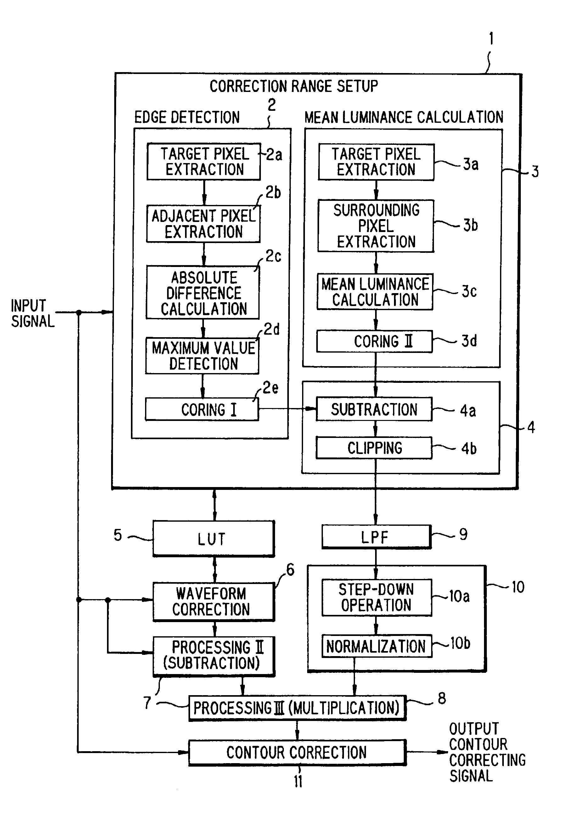
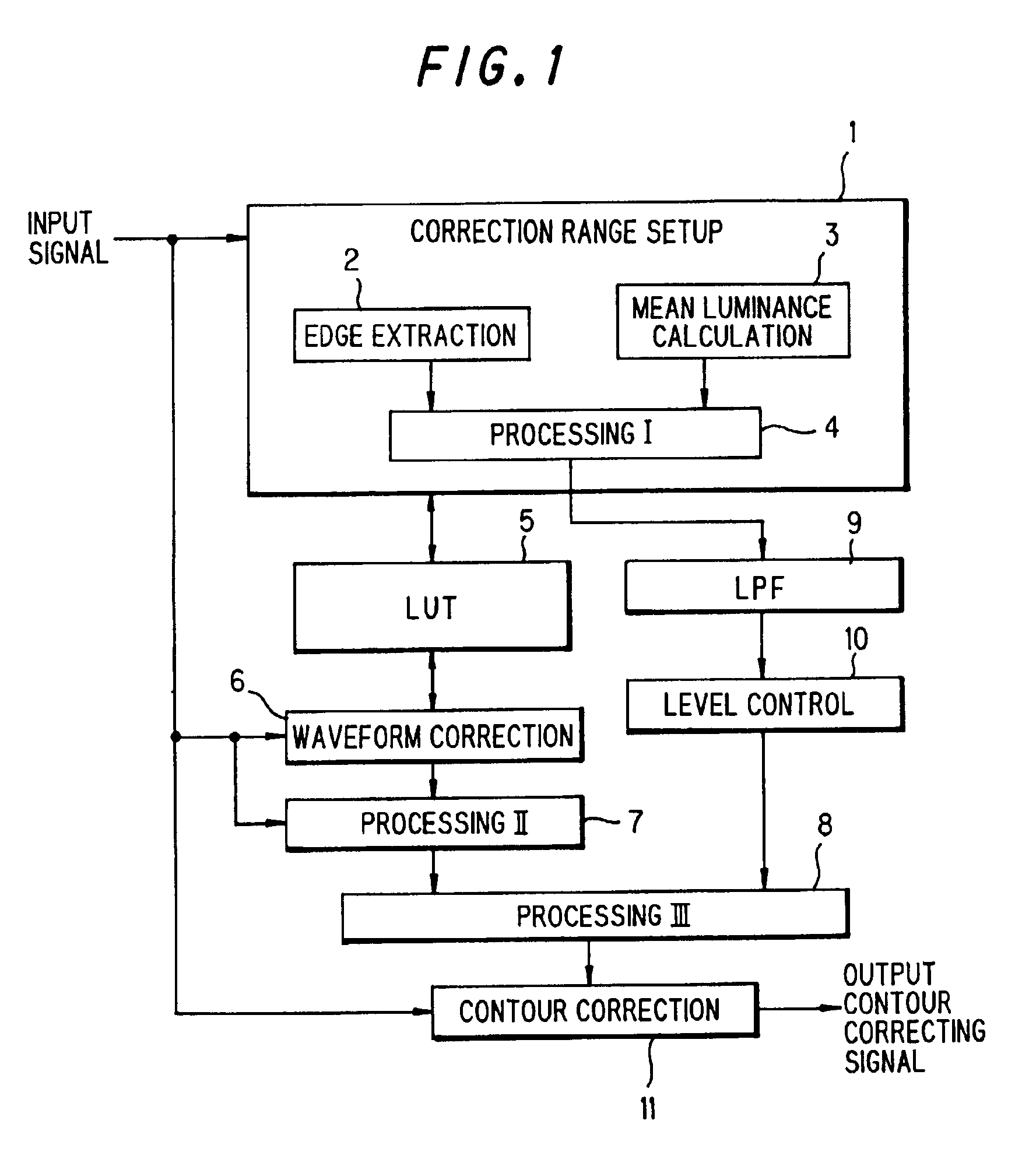
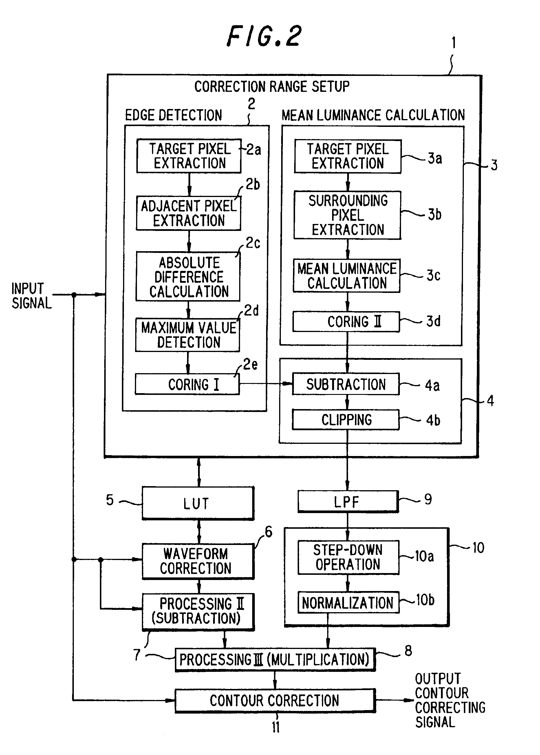
[0026]FIG. 1 is a block diagram showing the concept of a contour correcting device according to an embodiment of the present invention.

[0027]In FIG. 1, 1 designates a correction range setting portion for determining areas and ranges in which contour correction is to be done. This correction range setting portion 1 is comprised of an edge extractor 2, a mean luminance calculator 3 for detecting the mean luminance of a designated area and a first processor 4 that receives the outputs from the edge extractor 2 and mean luminance calculator 3 and performs predetermined operations.

[0028]Designated at 5 is a look-up table (which will be referred to hereinbelow as LUT) in which conversion characteristics, various threshold values are stored. FIGS. 3, 5 and 7 show the example of input / output characteristics. Reference numeral 6 designates a waveform corrector which converts the input signal ...


PUM


Abstract

Filtration of an input signal implemented in the horizontal or vertical direction may disorder the gradation in oblique directions, so that oblique lines may become jagged. To deal with this situation, the following components are provided to process the input signal: a waveform correcting means (6) having a correcting characteristic that the slope for correction in the medium-luminance range is greater than that in the high-luminance range or in the low-luminance range; a processing means (7) for extracting the deviation of the input signal processed by the waveform correcting means; a picture edge strength detecting means (1); and a processing means (8) for performing operations based on the deviation of the input signal and the picture edge strength.

Description

[0001]This application is the U.S. national phase of international application PCT / JP00 / 08428 filed 29 Nov. 2000, which designated the U.S.TECHNICAL FIELD[0002]The present invention relates to an image contour correcting device.BACKGROUND ART[0003]In the visual apparatus field, in order to improve image sharpness, contour correction circuits for correcting video signals have been used so as to emphasize contours of the picture signals.[0004]Conventionally used contour correction circuits generate a contour correction signal from high-frequency components which may be extracted from an input video signal, by passing it through a high-pass filter, by a differentiation process or the like, and superimpose the extracted contour correction signal over the delayed input video signal by an adder, to thereby produce a video signal enhanced in sharpness at contours.[0005]However, since the above usually used, conventional contour correction method performs contour correction by emphasizing t...

Claims


Application Information

Patent Timeline
IPC IPC(8): H04N5/208H04N5/262
CPCH04N5/208
Inventor HAMADA, SHOHICHIISHIMOCHI, HARUKI
Owner SHARP KK
Why Eureka
Eureka Blog
Learn More