Method and system for detecting object presence and its duration in a given area

a technology of object presence and duration, applied in the field of detection and monitoring techniques, can solve the problems of manual action, system typically does not capture data relating to customer or employee movement, inefficiency in time and manpower, etc., and achieve the effect of convenient installation

Inactive Publication Date: 2005-07-05
APPLIANCE SCI
View PDF32 Cites 108 Cited by
  • Summary
  • Abstract
  • Description
  • Claims
  • Application Information

AI Technical Summary

Benefits of technology

[0003]From the foregoing, it may be appreciated by those skilled in the art that a need has arisen to unobtrusively determine presence of an object, identify the object and determine its duration of presence within a given area. In accordance with the present invention, a method and system for unobtrusively determining presence of an object in a given area, identifying the object and determining its duration of presence, are provided that substantially eliminate or greatly reduce disadvantages and problems associated with conventional monitoring techniques.

Problems solved by technology

However, these systems typically require a manual action, such as data entry or product scanning, to capture the data.
In addition, these systems typically do not capture data relating to customer or employee movements within the business.
However, these systems typically require a manual action, such as the use of a passkey or the entry of a code to record employee presence, and are thereby limited in their application to businesses where requiring a manual action by the employee to record presence is desirable.
However, gathering customer or employee movement information through the use of video cameras requires someone to sit in front of a video display and watch the business operate.
This results in inefficiencies in time and manpower.
In businesses where knowledge of customer or object movement is desirable, video cameras do not provide sufficient information related to business operation in that there is no technique to determine quantitatively how effective employees in the business are performing their tasks and whether they are effectively working in their assigned areas.
A video camera implementation also has the limitation of requiring line of sight operation in order to effectively provide a monitoring capability.
Moreover, privacy issues come into play through the use of video camera surveillance.
However, these systems require significant electrical energy to operate and are limited in their ability to accurately discern proximity.
Accordingly, they are limited in their application and effectiveness.
However, these systems are limited in their effectiveness because ultrasound and infrared signals require line of sight access between the transmitter and receiver.

Method used


Image

  • Method and system for detecting object presence and its duration in a given area
  • Method and system for detecting object presence and its duration in a given area
  • Method and system for detecting object presence and its duration in a given area

Examples


Embodiment Construction

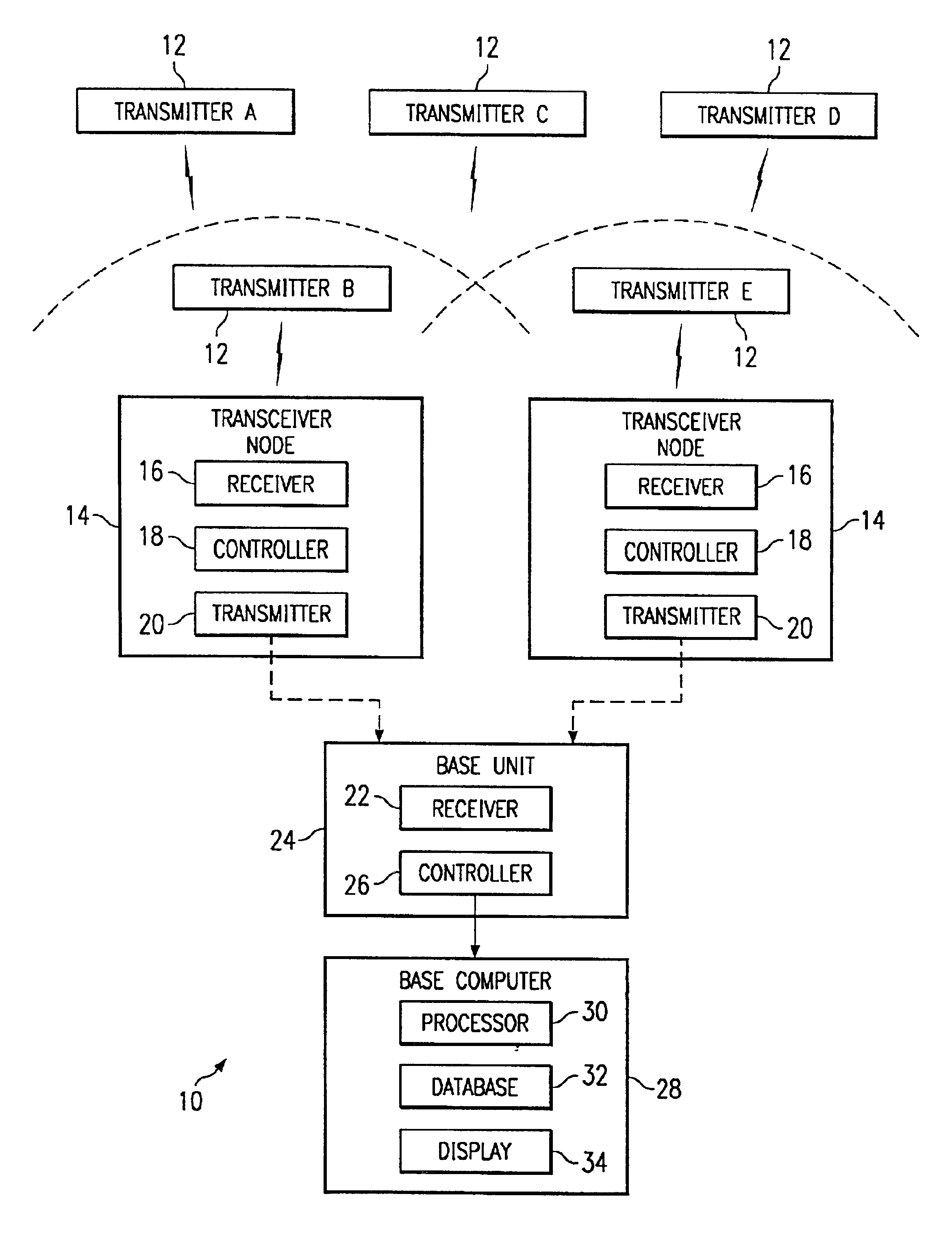
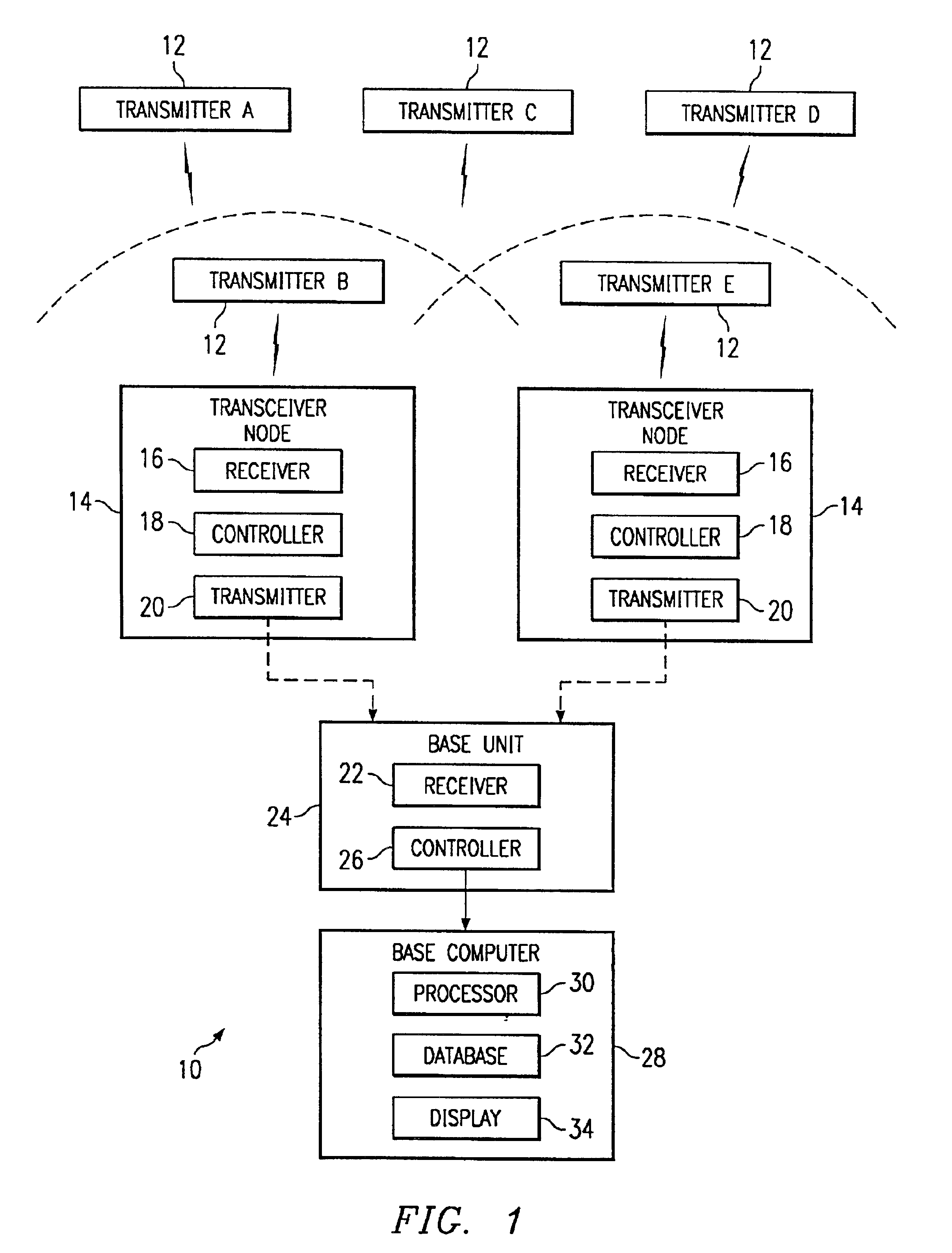
[0009]FIG. 1 is a block diagram of a system 10 for detecting a presence of an object and its duration in a given area. System 10 may include one or more mobile transmitters 12 that are capable of periodically transmitting a beacon signal. A beacon signal for a particular mobile transmitter 12 includes a unique identification code that makes it different from any other beacon signal transmitted by other mobile transmitters 12 within a particular environment or system installation. Preferably, the beacon signal transmitted by mobile transmitter 12 is a short burst transmission of one or more data packets that include the unique identification code. Mobile transmitter 12 preferably transmits the beacon signal every second of time, though other periodic transmission lengths may be used as desired. The beacon signal is preferably transmitted using radio frequency transmission techniques to eliminate line of sight requirements. The transmission power and / or frequency of mobile transmitter...


PUM


Abstract

A system (10) for determining a presence, identity, and duration of presence in a given area of an object includes one or more mobile transmitters (12) that periodically send out a beacon signal. A node (14) includes a receiver (16) that receives a beacon signal whenever a mobile transmitter (12) is within a threshold range of the node (14). The node (14) includes a controller (18) that determines a signal strength of each received beacon signal. The controller (18) compares the signal strength of each received beacon signal to a reference signal strength associated with the threshold range in order to determine whether the mobile transmitter (12) was within the desired detection area of the node (14). A base unit (24) sorts received information packets for processing by a base computer (28) in order to determine what mobile transmitter (12) was at what node (14) and for how long.

Description

TECHNICAL FIELD OF THE INVENTION[0001]The present invention relates in general to detection and monitoring techniques and more particularly to a method and system for detecting object presence, identifying the object and determining its duration of presence in a given area.BACKGROUND OF THE INVENTION[0002]In many businesses, it is desirable to monitor the operation of the business. Systems used to monitor business operations include transaction tracking, such as point of sale (POS) systems. These systems capture and process information relating to the purchase itself, such as salesperson, item purchased, product price and time of purchase. However, these systems typically require a manual action, such as data entry or product scanning, to capture the data. In addition, these systems typically do not capture data relating to customer or employee movements within the business. Other systems are designed to monitor customer or employee movements within a business operation, such as sec...

Claims


Application Information

Patent Timeline
Patent Type & Authority Patents(United States)
IPC IPC(8): H04Q7/20G01S7/00G01S13/78G01S13/87G08B13/14G08B21/02
CPCG01S7/003G01S13/78G01S13/876G08B13/1427G08B21/0202
Inventor MCKEE, PHILIP R.MOELLER, ERIC J.BAUER, FREDRICK L.
Owner APPLIANCE SCI
Why Eureka
Try Eureka