MEMS gyroscope having mass vibrating vertically on substrate

a gyroscope and vertical vibrating technology, applied in the direction of acceleration measurement using interia force, turn-sensitive devices, instruments, etc., can solve the problems of high possibility of malfunction, high manufacturing difficulty of the above structure of the electrodetector, adhesion between the moving electrode and the moving electrode, etc., to achieve highly precise control and simplify the manufacturing process

Inactive Publication Date: 2005-07-12
SAMSUNG ELECTRONICS CO LTD
View PDF4 Cites 77 Cited by
  • Summary
  • Abstract
  • Description
  • Claims
  • Application Information

AI Technical Summary

Benefits of technology

[0015]The present invention has been made to overcome the above-mentioned problems. Thus, an aspect of the present invention is to provide an X type MEMS gyroscope with easy manufacturability and less malfunction probability.
[0020]According to the present invention, all moving electrodes and stationary electrodes are disposed on the same surface of the substrate. Accordingly, all elements can be manufactured with a single mask, thus the manufacturing process is simplified.
[0021]Further, the distance between the moving electrode and the stationary electrode can be narrowed without causing adhesion of the moving electrode and the stationary electrode. Accordingly, the gyroscope of highly precise control can be realized.

Problems solved by technology

Yet, the electrode having the above structure is very difficult to manufacture as the moving electrode 13 is suspended above the upper part of the stationary electrode 11.
Therefore, there is a problem that adhesion can be created between the moving electrode 13 and the stationary electrode 11.
1 requires many steps in manufacturing and has a high possibility of malfunction due to the adhesion.

Method used


Image

  • MEMS gyroscope having mass vibrating vertically on substrate
  • MEMS gyroscope having mass vibrating vertically on substrate
  • MEMS gyroscope having mass vibrating vertically on substrate

Examples


Embodiment Construction

[0034]From now on, the present invention will be described in greater detail by referring to the appended drawings.

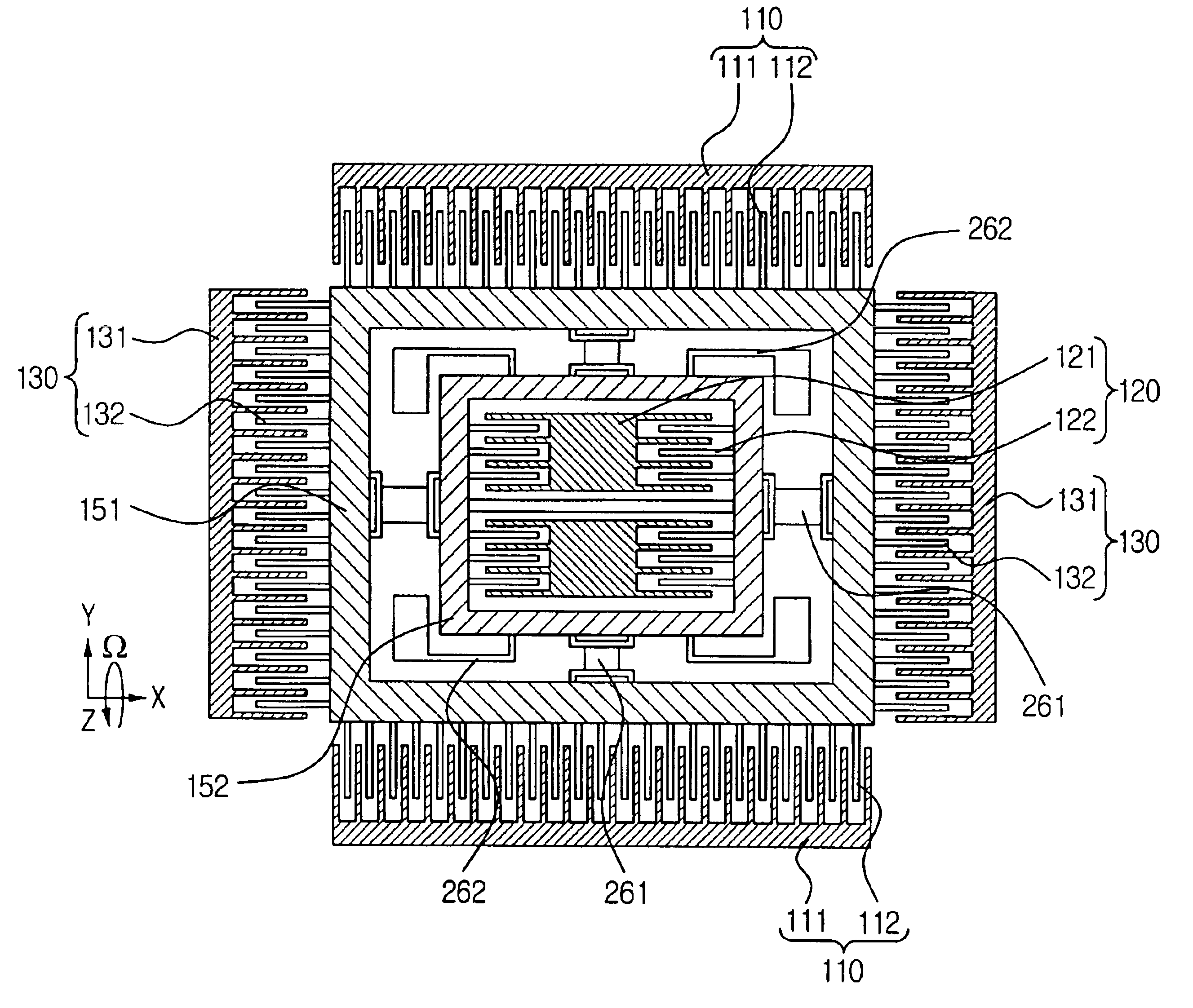
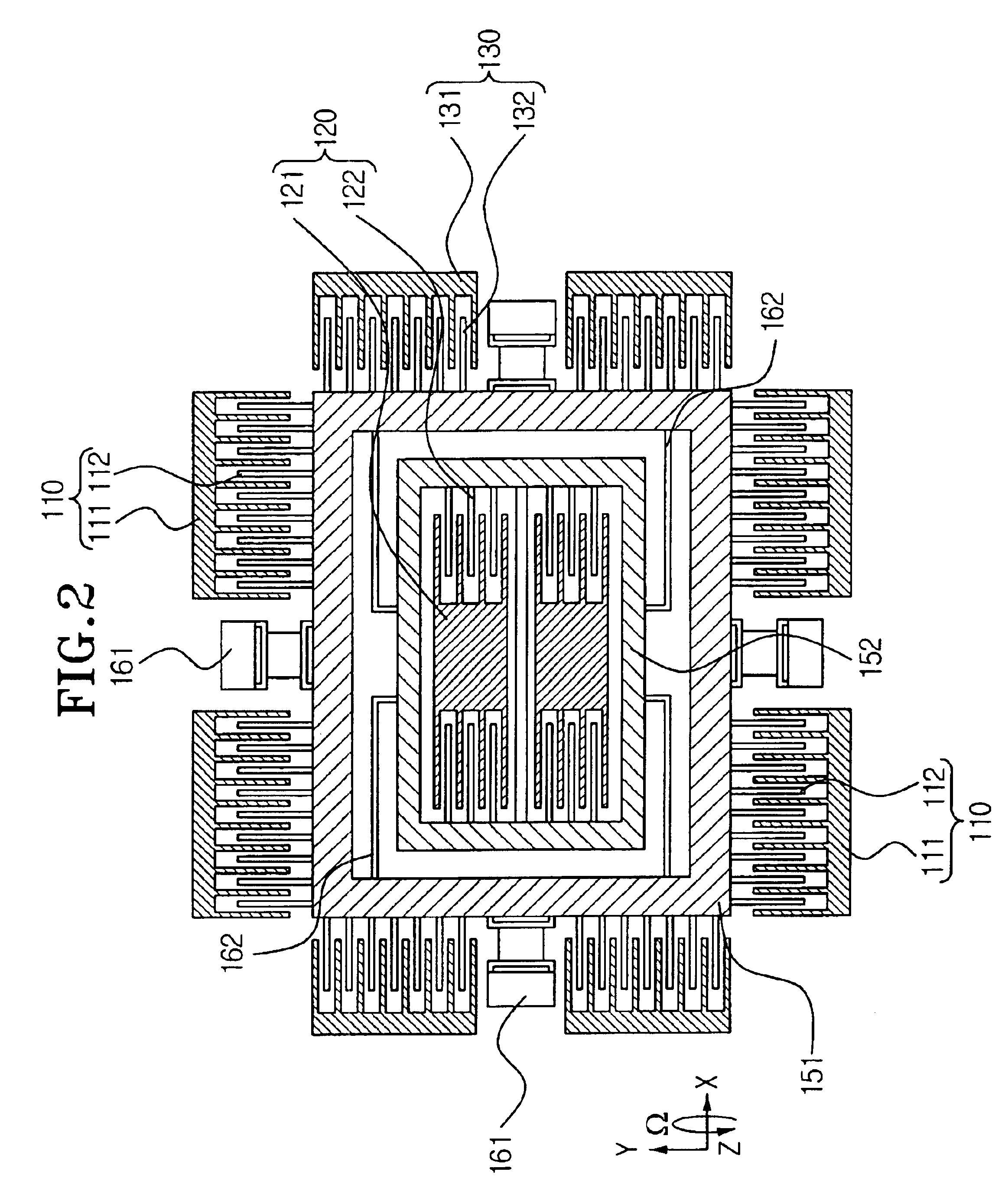
[0035]As mentioned in the description part of the prior art, the direction that a mass is driven in a gyroscope is a ‘driving direction,’ the direction that angular velocity is input into the gyroscope is an ‘input direction’ and the direction that Coriolis force generated in the mass is sensed is a ‘sensing direction.’ Moreover, the direction at a right angle to a surface of a substrate is a ‘vertical direction’ and the direction parallel to the surface of the substrate is a ‘horizontal direction.’ In the meantime, the right and left directions of the horizontal direction in the Figures are the ‘X direction,’ the up and down directions in the Figures are the ‘Y direction,’ and the vertical direction and ‘Z direction’ are used as having the same meaning.

[0036]FIG. 2 is a view showing the first exemplary embodiment of a MEMS gyroscope according to the present invention.

[...


PUM


Abstract

X type MEMS gyroscope has a first mass vertically vibrating on a substrate and a second mass horizontally vibrating on the substrate. A driving electrode is disposed on the same surface with the first mass. The first mass can move in relation to the second mass in the vertical direction, and is fixed in relation to the second mass in the horizontal direction. The second mass is operative to be moved in a horizontal direction in relation to the substrate by a Coriolis force, which is generated by an angular velocity applied while the first mass is being vibrated. A sensing electrode measures displacement of the second mass in the horizontal direction. All moving electrodes and stationary electrodes are disposed on the same surface, and all elements are manufactured by using one mask. Therefore, adhesion between the moving and stationary electrodes is prevented and the manufacturing process is simplified.

Description

CROSS-REFERENCE[0001]The present application is based on Korean Patent Application No. 2001-79496, which is incorporated herein by reference.BACKGROUND OF THE INVENTION[0002]1. Field of the Invention[0003]The present invention relates to a MEMS gyroscope, and more particularly, to a MEMS gyroscope having a mass vibrating vertically on a substrate.[0004]2. Description of the Related Art[0005]MEMS (micro electro mechanical system) is a technology realizing mechanical and electric elements using a semi-conductor process. One example of an element using MEMS technology is a gyroscope for measuring angular velocity. The gyroscope measures the angular velocity by measuring Coriolis force generated when rotation angular velocity is added to an object moving with a predetermined velocity. The Coriolis force is proportional to a cross product of the rotation angular velocity due to external force and moving velocity.[0006]For the gyroscope to generate and sense the Coriolis force, the gyrosc...

Claims


Application Information

Patent Timeline
Patent Type & Authority Patents(United States)
IPC IPC(8): G01C19/56G01C19/5762
CPCG01C19/5762G01C19/56
Inventor KIM, JUN-OLEE, SANG-WOO
Owner SAMSUNG ELECTRONICS CO LTD
Why Eureka
Try Eureka