Single-piece snap-on connection

a single-piece, snap-on technology, applied in the direction of couplings, pipe elements, mechanical equipment, etc., can solve the problems of increasing the cost, permanent set, or even destruction of the linking arms, and the manufacture of more complicated, etc., to achieve the effect of long life and easy operation

a single-piece, snap-on technology, applied in the direction of couplings, pipe elements, mechanical equipment, etc., can solve the problems of increasing the cost, permanent set, or even destruction of the linking arms, and the manufacture of more complicated, etc., to achieve the effect of long life and easy operation

US6916050B2Inactive Publication Date: 2005-07-12NOBEL PLASTIQUES

Image

  • Single-piece snap-on connection
  • Single-piece snap-on connection

Examples


Embodiment Construction

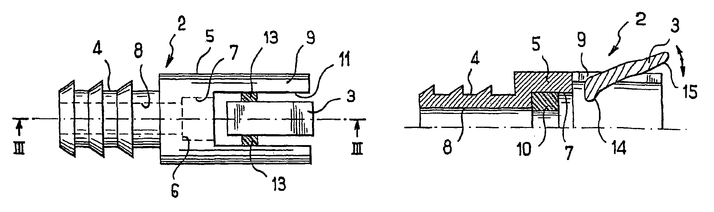
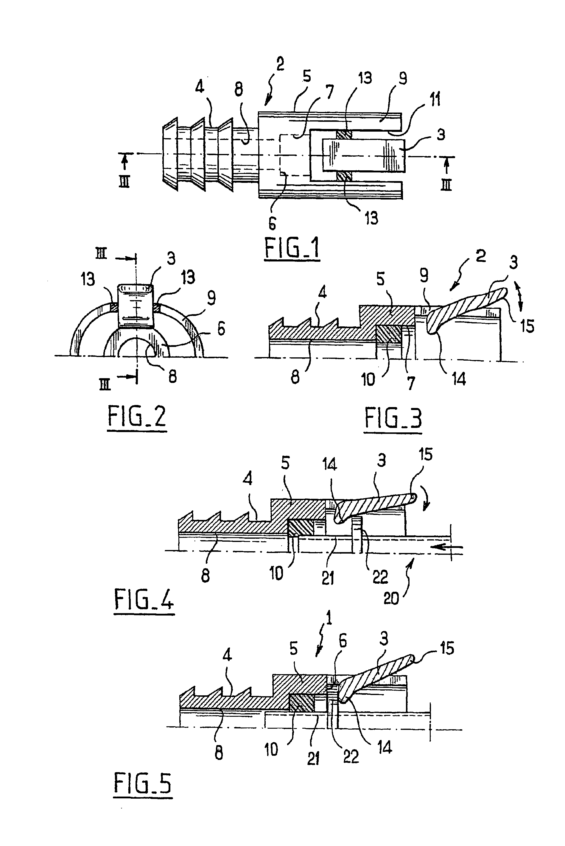
[0020]The coupler 1 comprises a body 2 made of a rigid plastic and a fastening part or lock 3, also made of a rigid plastic.

[0021]The body 2 has, at the rear, a hollow cannelated tail 4, in the form of fir tree teeth as shown or a doubly bulbous tail, designed to be force-fitted into a pipe, and, at the front, a cylindrical cup 5 forming, with the tail, a cylindrical cavity 7, 8 with one or more steps 6. The cylindrical cup 5 is extended over at least part of its periphery by a thinner skirt 9, which is approximately cylindrical, an upper part of which includes a broad notch 11 for housing the rectangular lock 3. The latter is connected to the sidewalls of the notch 11, and therefore to the skirt 9, by two flexible pivots 13 made by dual, plastic-elastic, injection molding. The two pivots 13 lie on an axis orthogonal to the longitudinal axis of the body 2, so as to make the lock 3 rock in or parallel to a plane passing through the axis of the body 2 (the plane of FIGS. 3, 4 and 5). ...


PUM


Abstract

A female snap-on connection is provided for cooperating with a male catching end piece with central barrel and flange ring. The snap-on connection includes a body made of rigid plastic material and a tubular portion with raised parts for connection to a pipe and a portion forming a stepped cylindrical cavity to receive at least the barrel end, and at the front of the body, a lock made of rigid plastic material to be urged to lock the flange ring once the latter is set in plane, the lock and the body are secured together by at least a flexible part so as to form a single piece, at least an annular joint ensuring tightness; the lock tilts on a hinge pin formed by the flexible part(s).

Description

FIELD OF THE INVENTION[0001]The present invention relates to a female snap coupler for cooperating with a flanged male fastening end-fitting.BACKGROUND INFORMATION[0002]It is usual, in particular in the automobile industry, to use snap couplers for the rapid connection of a fluid (for example fuel, oil or water) circuit element to another circuit element and for disconnection therefrom. In a substantially standardized manner, the industry uses male end-fittings having a cylindrical barrel surrounded by a flange, and the female couplers have a stepped cylindrical cavity, for housing at least the end of the barrel, and a resilient lock for locking the rear of the flange once the latter is in place. O-ring seals ensure sealing.[0003]In most commercial couplers, the body of the coupler, generally made of molded thermoplastic, the lock, more often than not also made of a molded thermoplastic or possibly a metal, and the seals, generally made of an elastomer, consist of separate parts tha...

Claims


Application Information

Patent Timeline
12 Jul 2005
Publication
US6916050B2
IPC
F16L37/098; F16L37/00
CPC
F16L37/096
Inventors
MILHAS, PIERRE