Medical valve with positive flow characteristics

a technology of positive flow and medical valve, applied in the field of medical valve, can solve the problems of unsatisfactory movement of fluid, medical device is disconnected from the valve, and prior art valve suffer from a problem, so as to prevent blood from flowing

Inactive Publication Date: 2005-07-12
ICU MEDICAL INC
View PDF166 Cites 114 Cited by
  • Summary
  • Abstract
  • Description
  • Claims
  • Application Information

AI Technical Summary

Benefits of technology

[0020]In accordance with another preferred embodiment there is provided a method of preventing blood from flowing out of a patient into a catheter when a syringe is withdrawn from a valve between the syringe and the catheter. The method comprises the steps of connecting the downstream end of the valve to the catheter and inserting the end of the syringe into a slit forming the upstream end of a normally substantially closed seal passage that is located in a resilient seal and is in fluid communication with the downstream end of the valve

Problems solved by technology

Unfortunately, prior art valves suffer from a problem arising from the disconnection of these medical devices from the valve.
A problem arises when the medical device is disconnected from the valve.
In the medical setting, this movement of fluid is very undesirable.
A serious problem may result in that this blood may clot and clog the catheter near its tip, rendering it inoperable, and may even result in a clot of blood in the patient, which may prove fatal.
This method has generally been unsuccessful in preventing clogging of the catheter.
The risk of blood clogging of the catheter is significantly heightened where

Method used


Image

  • Medical valve with positive flow characteristics
  • Medical valve with positive flow characteristics
  • Medical valve with positive flow characteristics

Examples


Embodiment Construction

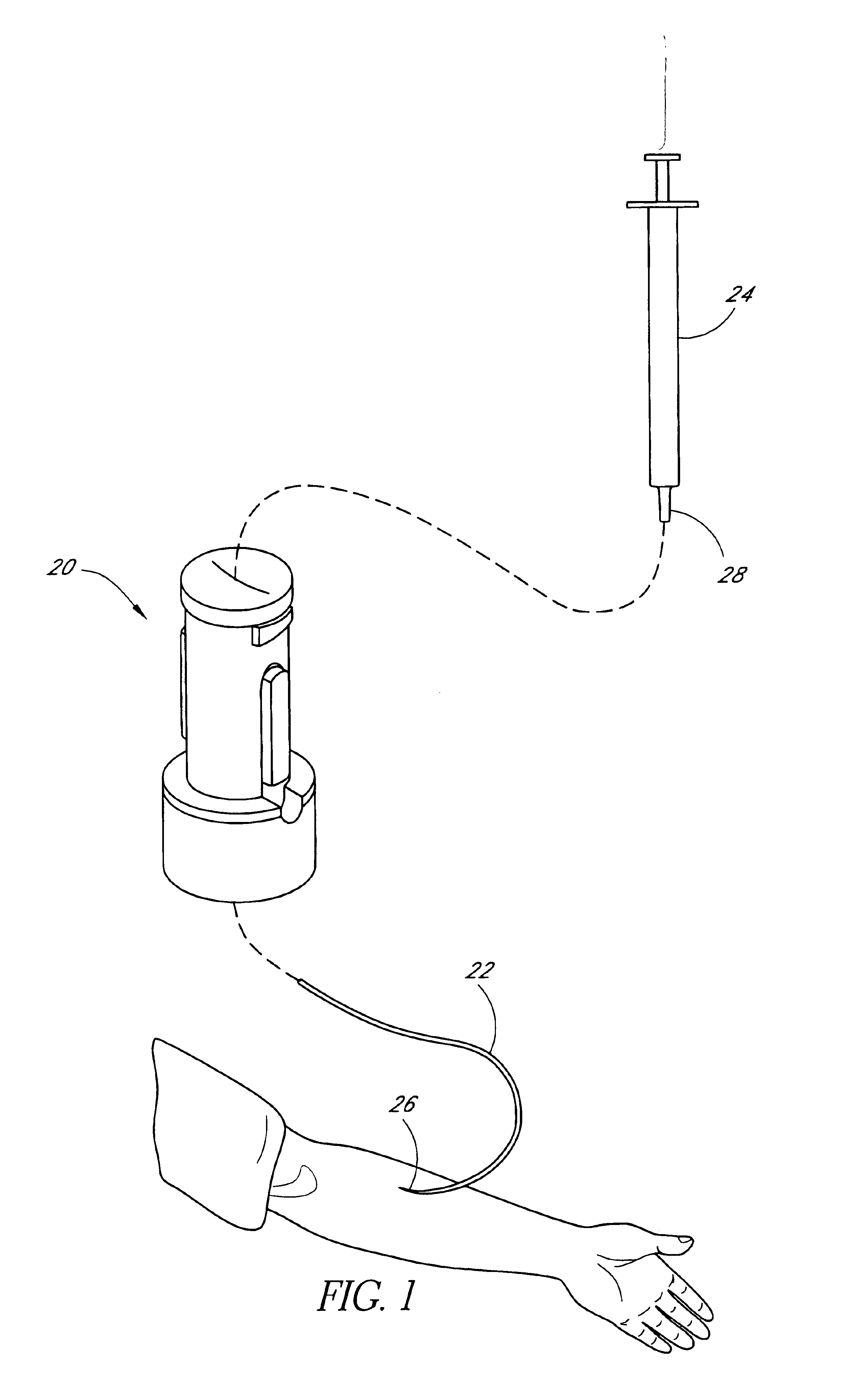
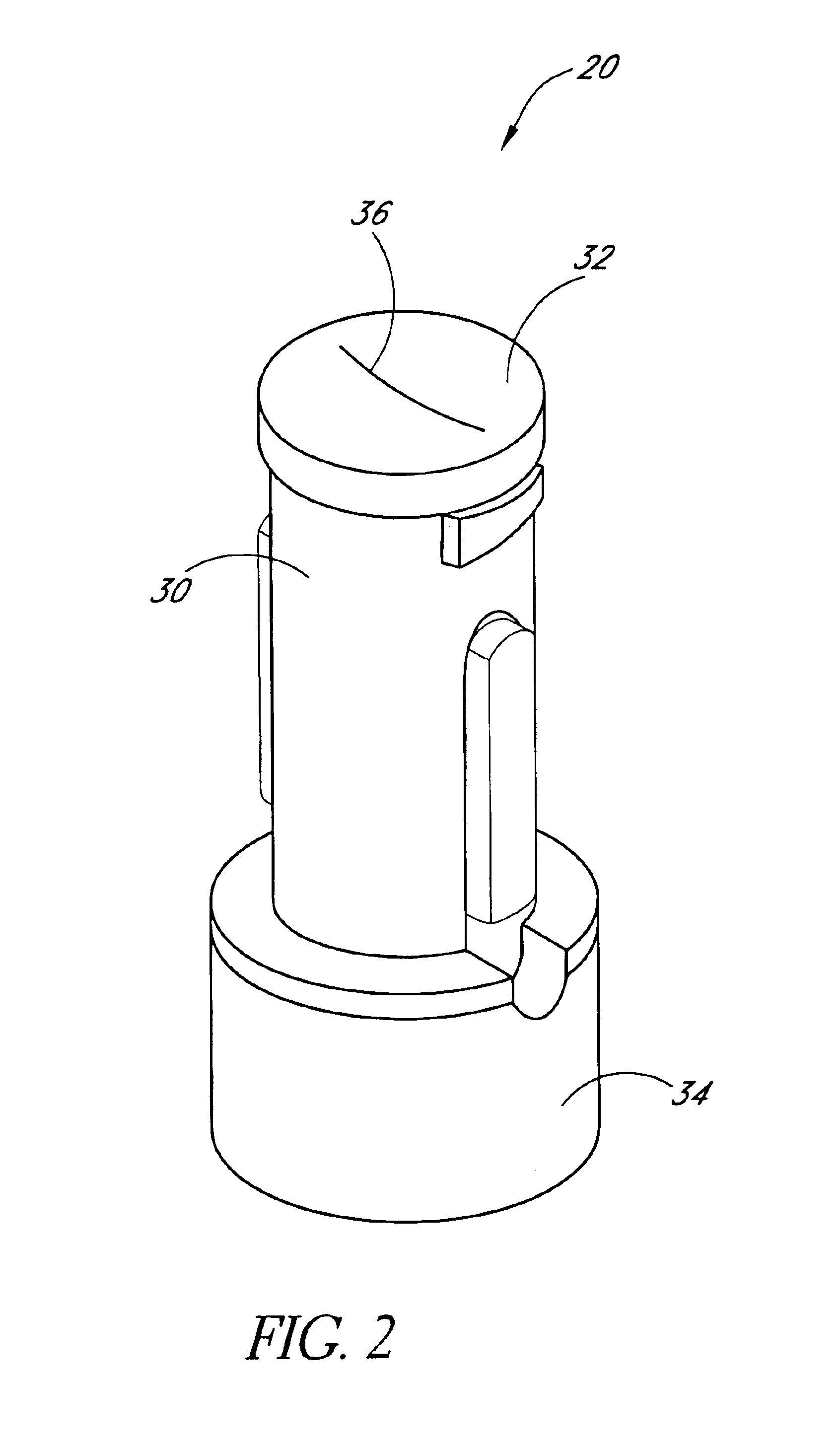
[0050]FIGS. 1-9 depict a valve 20 in accordance with a preferred embodiment of the invention. FIG. 1 illustrates a particular use of the valve 20 to which it is well suited. Of course, the valve 20 may be used in a variety of other manners.

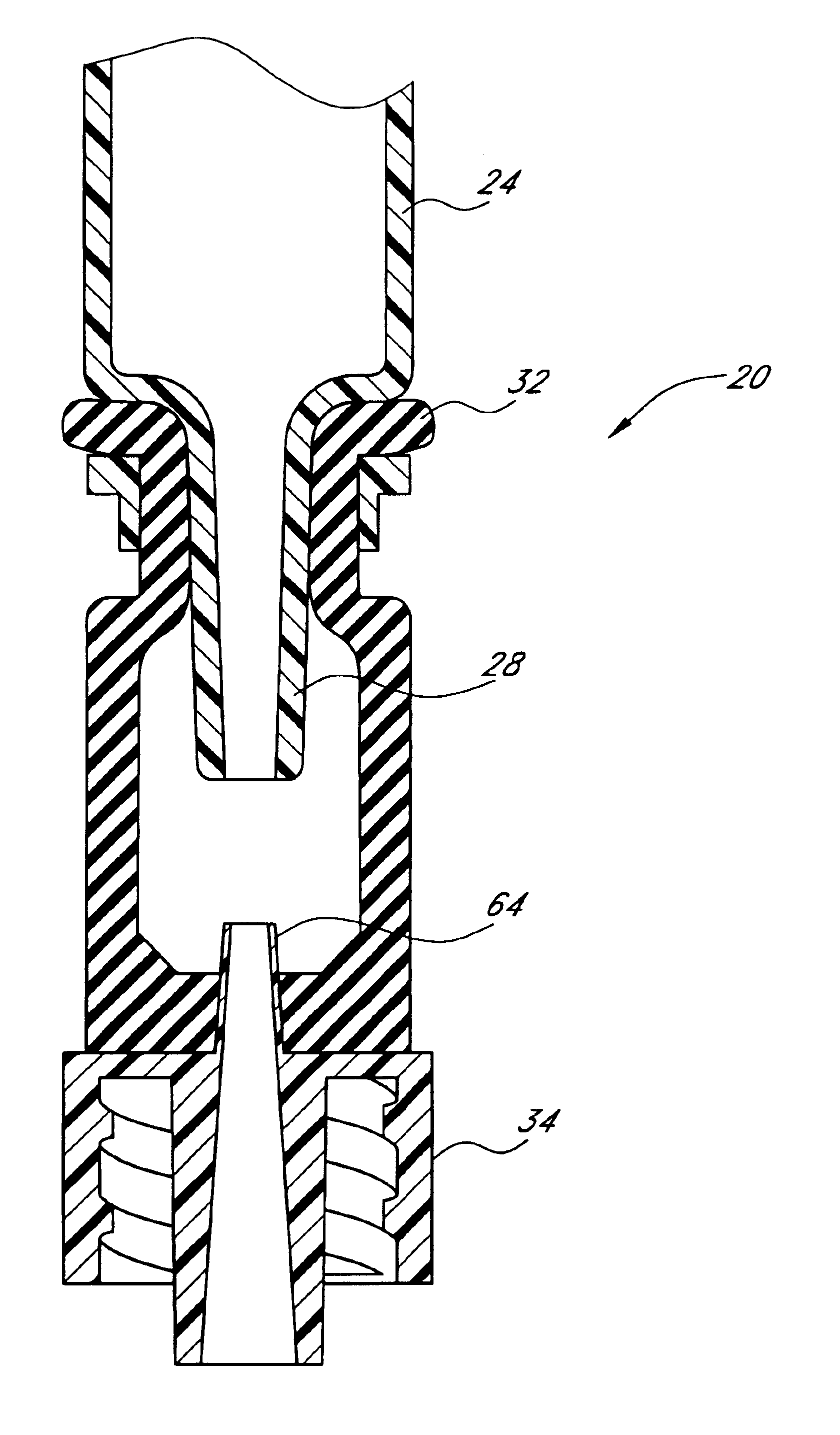
[0051]As illustrated in FIG. 1, the valve 20 may advantageously be used to selectively control the flow of fluid to a first medical device (such as a catheter 22 shown here) from a second medical device (generally comprising a fluid source such as an ISO standard syringe 24). In this arrangement, the catheter 22 is connected to one end of the valve 20 and has a tip 26 inserted into the arm of a patient. The syringe 24 has a cannula tip or Luer 28 that is inserted into the other end of the valve 20, which is designed to accept the Luer 28 of the syringe 24 without a needle installed on the Luer.

[0052]When so connected, the valve 20 permits fluid to flow from the syringe 24 to the catheter 22 and into the patient. The valve 20 is also arranged so th...


PUM


Abstract

A valve for selectively permitting a fluid flow between first and second medical implements is disclosed. The valve has a housing with an interface suitable for receiving a connector portion of a first medical device such as a catheter, and a seal made of a flexible material. The seal has a first end in fluid communication with the interface, a second end suitable for receiving the second medical device, and at least one slit in fluid communication with the first end and the second end. The slit defines a restricted fluid flow path and a relatively small interior volume when in an undisturbed state, defines an expanded fluid flow path and a larger interior volume upon the introduction of the second medical instrument into the slit, and retracts to define a restricted flow path and a small interior volume upon the withdrawal of the second medical device from the seal.

Description

RELATED APPLICATION[0001]This application is a continuation of U.S. patent application Ser. No. 09 / 614,001, filed Jul. 11, 2000 now U.S. Pat. No. 6,695,817.BACKGROUND OF THE INVENTION[0002]1. Field of the Invention[0003]This invention relates generally to a medical valve, and in particular to a valve which, when connected between a first medical device, such as a fluid source, and a second medical device, such as a catheter, facilitates fluid flow therebetween, and when the first medical device is disconnected therefrom, induces a positive flow of fluid through the valve in the direction of the second medical device.[0004]2. Description of the Related Art[0005]The manipulation of fluids for parenteral administration in hospitals and medical settings routinely involves the use of connectors and valves for selectively facilitating the movement of fluids between two points. These valves are typically placed along a fluid flow line leading to a patient or other destination. For example,...

Claims


Application Information

Patent Timeline
IPC IPC(8): A61M39/02A61M39/26A61M39/04A61M39/00A61M5/168A61M25/18A61M31/00
CPCA61M39/02A61M39/045A61M39/26A61M39/10A61M2039/263A61M39/00A61M39/0247A61M39/06A61M2039/0205A61M2039/0258A61M2039/027A61M2039/062
Inventor FANGROW, JR., THOMAS F.
Owner ICU MEDICAL INC
Why Eureka
Try Eureka