Uninterruptible power supply

Inactive Publication Date: 2005-07-12
VERTIV CORP
View PDF3 Cites 125 Cited by
  • Summary
  • Abstract
  • Description
  • Claims
  • Application Information

AI Technical Summary

Benefits of technology

[0009]In another aspect of the invention relating to control of the rectifier, there is a method of controlling the output of the controlled rectifier. The method includes, sensing the voltage on the DC bus at the rectifier's output, comparing the sensed voltage to a voltage setpoint, increasing or decreasing the rectifier firing angle to minimize a difference between the sensed voltage and the voltage setpoint, and determining whether an input current of the rectifier or a charging current of the battery is above a predetermined limit; and, if so, switching control to a different control loop to maintain the input current or the charging current within the predetermined limit. In implementing this method, it is beneficial to pre-load the integrator of the different control loop when switching to a differ

Problems solved by technology

Historically, uninterruptible power supplies have relied on traditional analog control techniques, which are limiting in the l

Method used


Image

  • Uninterruptible power supply
  • Uninterruptible power supply
  • Uninterruptible power supply

Examples


Example

I. UPS Topology

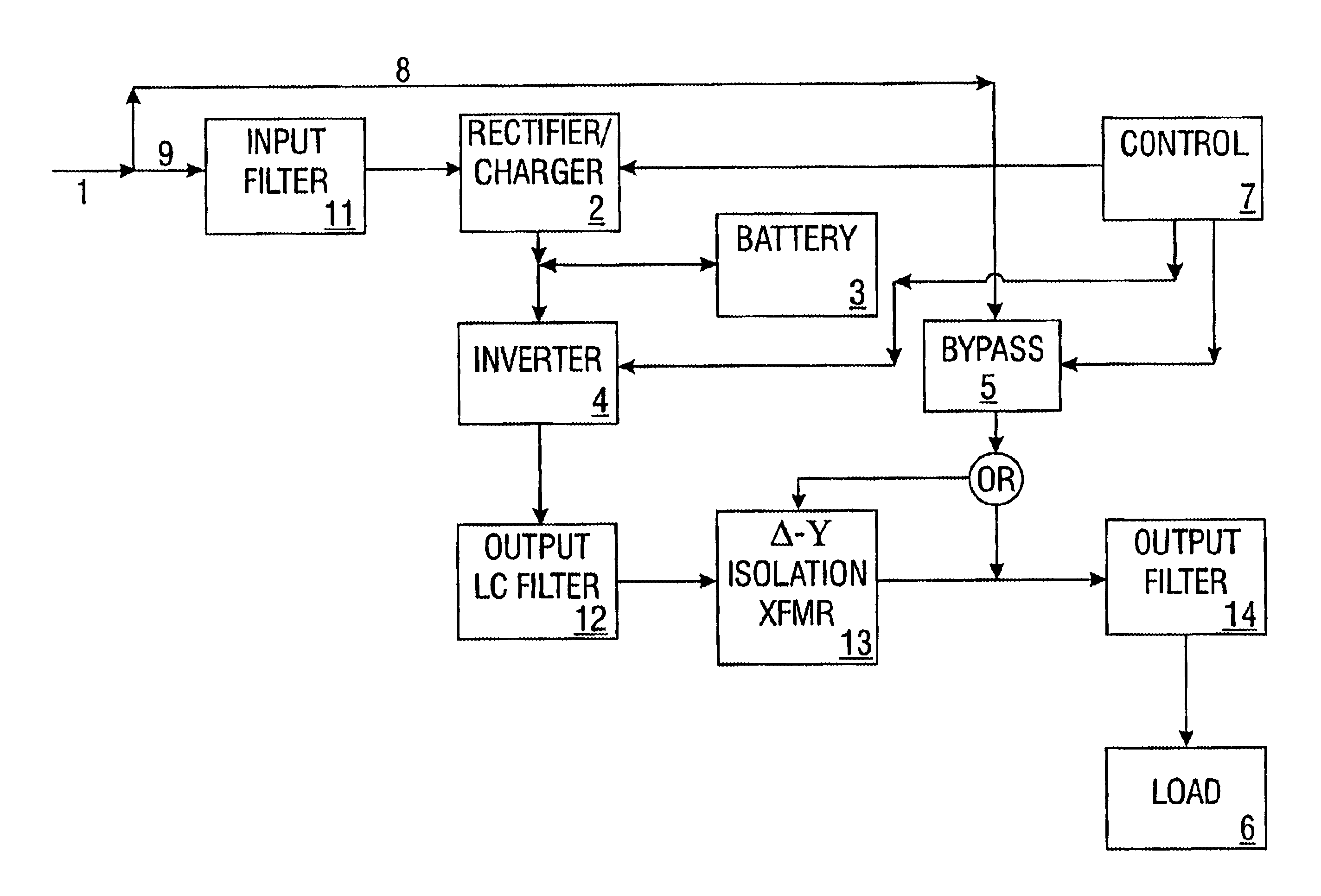
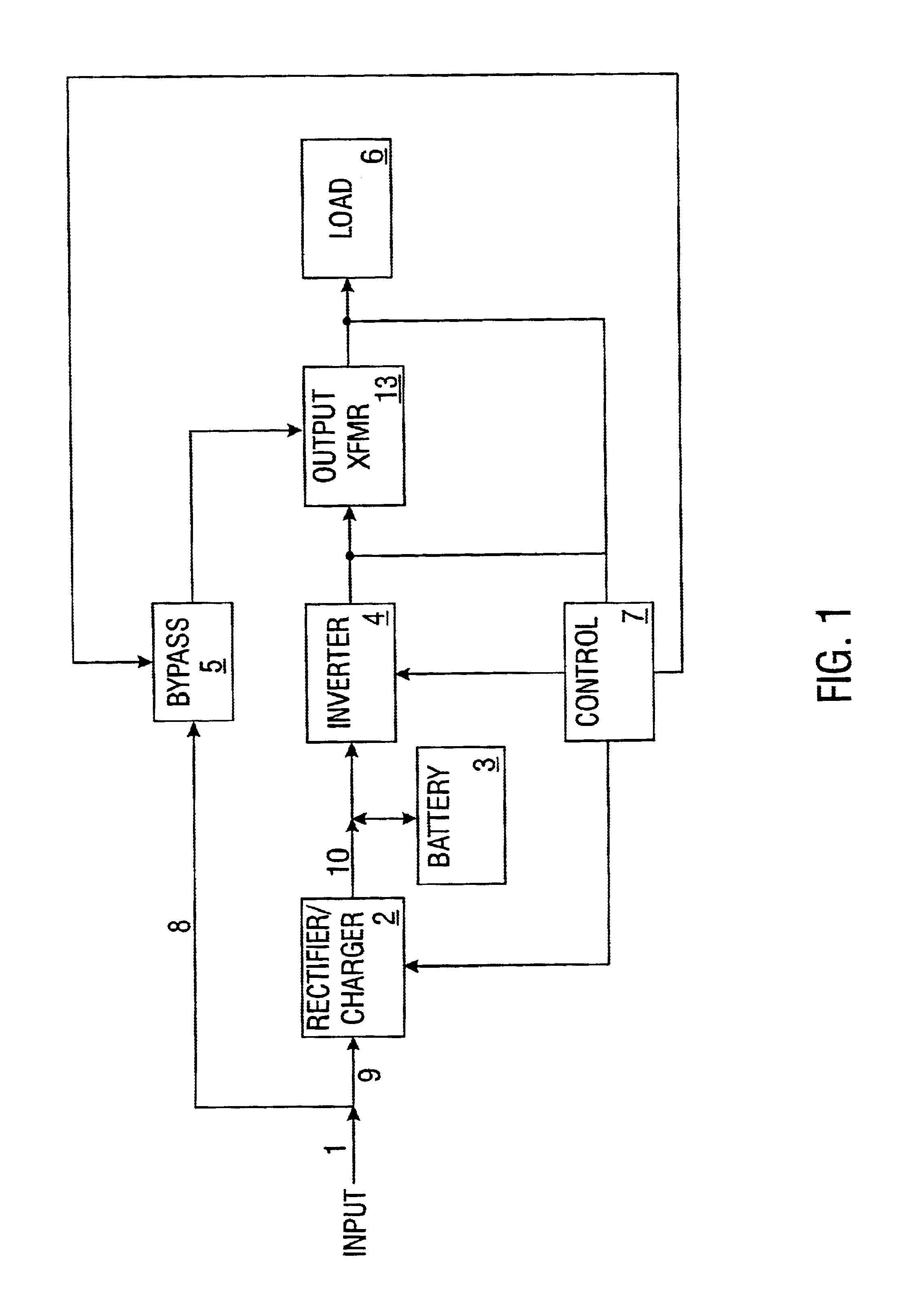
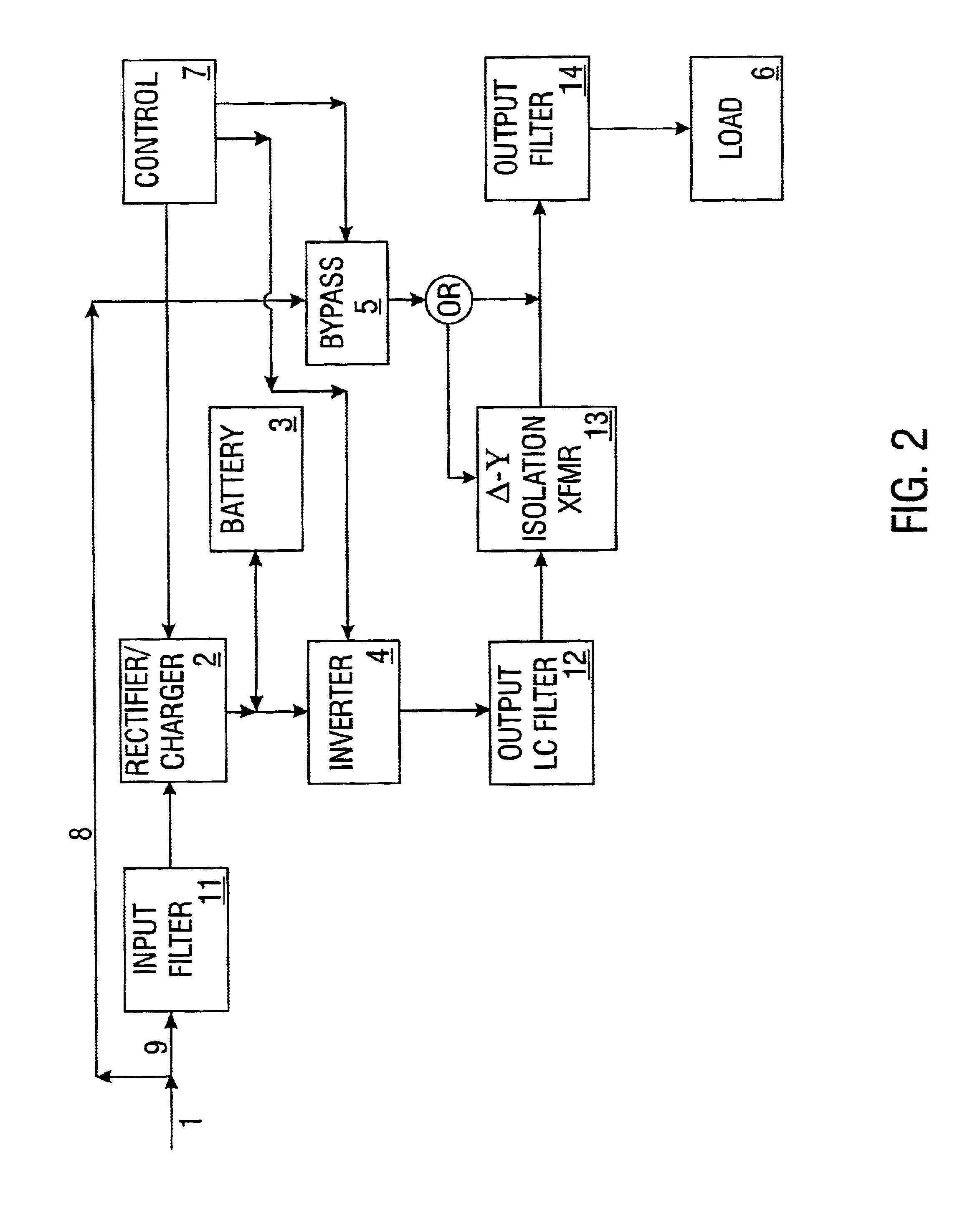
[0051]An uninterruptible power supply (“UPS”) in accordance with the present invention is illustrated in FIG. 1. The UPS includes the rectifier / charger 2, battery 3, DC bus 10, inverter 4, bypass switch 5, control module 7, and output transformer 13. Under normal operating conditions, alternating current (“AC”) power is supplied at the input 1. The AC power follows the first power path 9 to the rectifier / charger 2. The rectifier / charger 2 converts the incoming AC voltage to a direct current (“DC”) voltage. This DC voltage is supplied to battery 3 to charge the battery. The DC voltage is also supplied to the DC bus 10, which powers inverter 4. Inverter 4 converts the supplied DC voltage to an AC voltage that is then supplied to the load 6 via the output transformer 13.

[0052]If one of the UPS components fails or if the UPS power rating is insufficient to power load 6, power flows from the input 1, along a second power path 8, to bypass switch 5. Bypass switch 5 is close...


PUM


Abstract

An uninterruptible power supply is disclosed that includes a digital controller comprising a plurality of microprocessors. These microprocessors are programmed and arranged to provide various control features heretofore unavailable using analog controllers of the prior art.

Description

CROSS REFERENCE TO RELATED APPLICATION[0001]This application claims the benefit of U.S. Provisional Application Ser. No. 60 / 244,005, filed Oct. 27, 2000.BACKGROUND OF THE INVENTION[0002]The present invention relates to uninterruptible power supplies, and, in particular, the control of uninterruptible power supplies. Historically, uninterruptible power supplies have relied on traditional analog control techniques, which are limiting in the level of control that can be provided and in the aspects of the uninterruptible power supply's operation that can be controlled. Accordingly, what is needed in the art is an uninterruptible power supply featuring digital control, which allows greater flexibility and more precise control of the uninterruptible power supply.SUMMARY OF THE INVENTION[0003]In one aspect the present invention is directed to an uninterruptible power supply comprising a controlled rectifier a battery an inverter and a control system. The control system is coupled to the co...

Claims


Application Information

Patent Timeline
IPC IPC(8): H02J9/06
CPCH02J9/061H02J9/062
Inventor SHETLER, JR., RUSSELL EDWARDHEBER, BRIAN PAULESCHHOFEN, KEVIN KIMSUBRAMANIAN, RAMESHNORRIS, NELSON JOHNRAUTENSTRAUCH, RONALD RICHARDFUNK, JON ROSSBELL, KEVIN JAYSHENOY, SURATKAL PADMANABHABUSH, TERRY DWANEKAFAIPOUR, FARZINMARWALI, MOHAMMAD NANDA RAHMANAMARGRAFF, ANDY
Owner VERTIV CORP
Why Eureka
Try Eureka