Concurrent dual-band receiver architecture

a receiver and dual-band technology, applied in the field of high-frequency receivers, can solve the problems of insufficient multi-functional device next-generation, inconvenient operation, and inefficient components of the receiver, so as to increase reduce the cost and footprint, and reduce the effect of power consumption

Inactive Publication Date: 2005-07-12
CALIFORNIA INST OF TECH
View PDF15 Cites 87 Cited by
  • Summary
  • Abstract
  • Description
  • Claims
  • Application Information

AI Technical Summary

Problems solved by technology

While such functionality adds to a device's versatility, such as in the case of a dual-band digital cellular phone, these receivers are very inefficient in terms of component parts and power consumption and would not satisfy the needs for the next-generation of multi-functional devices, such as a cell phone with a GPS receiver and a bluetooth interface.
Another problem with conventional wireless technology relates to bandwidth limitations.
Unfortunately, these modes of operation are of limited functionality because they limit the system's available bandwidth and robustness to channel variations.
On the other hand, wide-band modes of operation are more sensitive to out-of-band signals due to transistor non-linearity, which can introduce severe bottlenecks in system performance.
A further challenge for modem receiver design is to create true concurrent dual-band functionality using as little real estate (and ideally monolithically) and as little power dissipation as possible (and perhaps no more than single band receivers), while keeping the incremental production costs above the conventional single band receiver to a minimum.

Method used


Image

  • Concurrent dual-band receiver architecture
  • Concurrent dual-band receiver architecture
  • Concurrent dual-band receiver architecture

Examples


Embodiment Construction

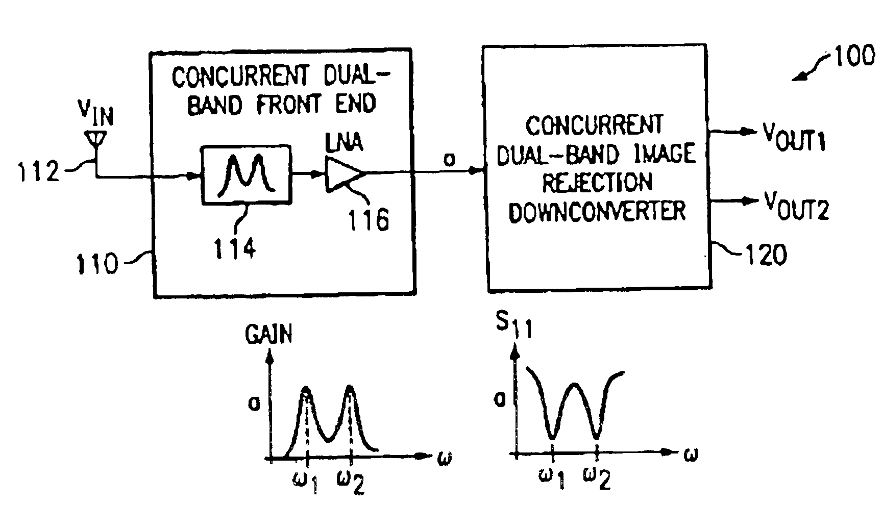
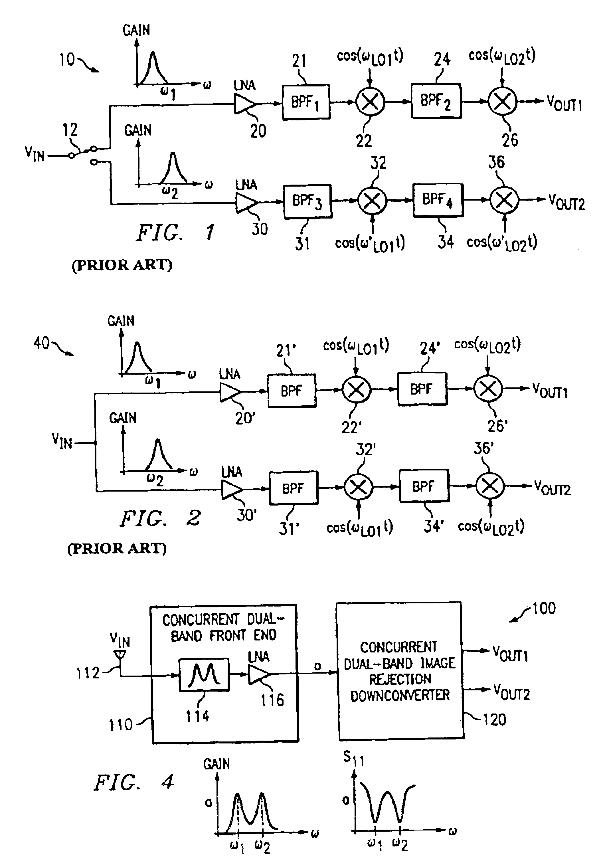
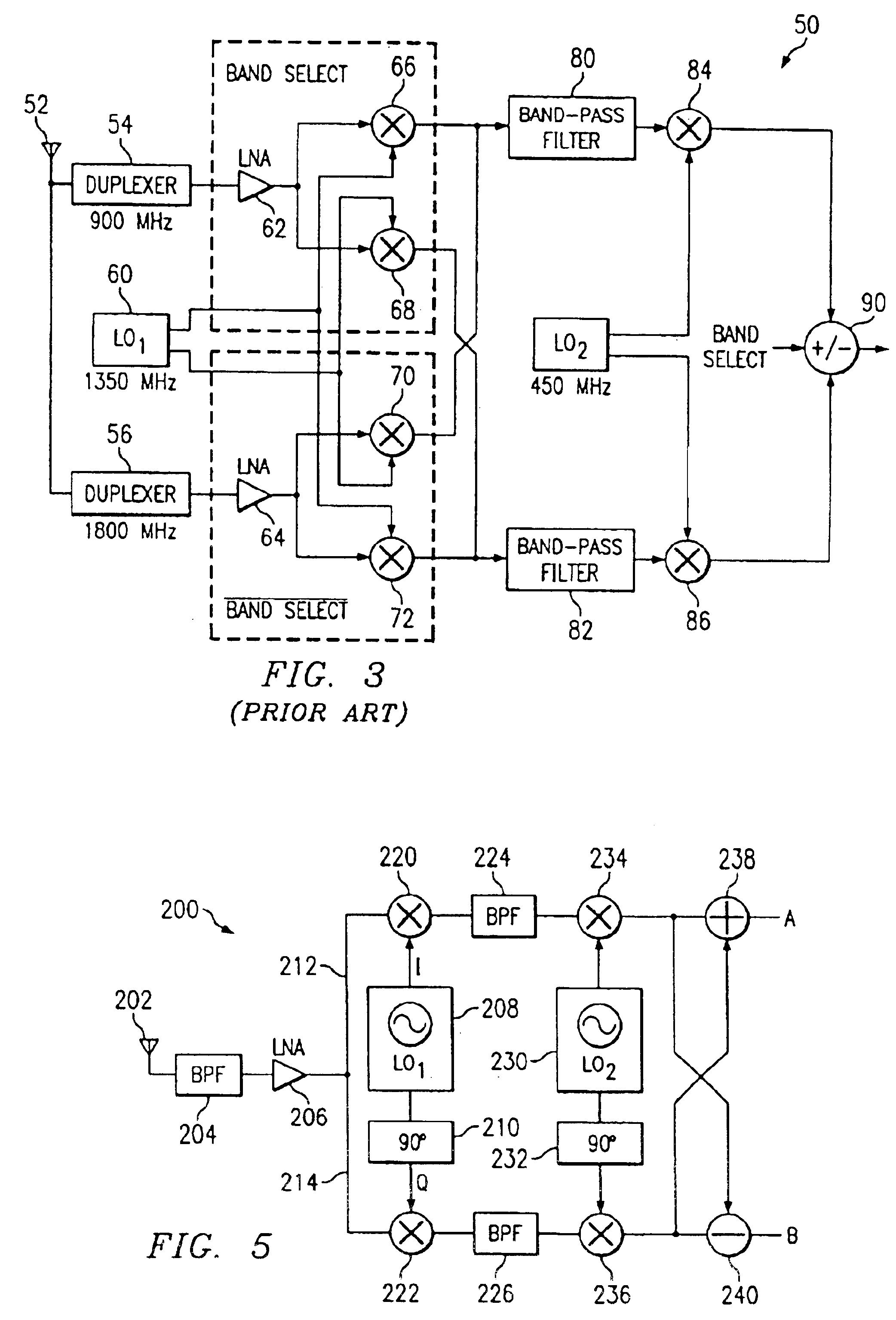
[0043]The invention summarized above and defined by the enumerated claims may be better understood by referring to the following detailed description, which should be read in conjunction with the accompanying drawings. This detailed description of particular preferred embodiments, set out below to enable one to build and use particular implementations of the invention, is not intended to limit the enumerated claims, but to serve as a particular examples thereof. The particular example set out below is the preferred specific implementations of a concurrent dual-band high frequency RF receiver and methods for designing the same. It should be understood however, that this system and technique is not limited to dual-band receivers, but may be extended to other applications, such as transmitters and transceivers. It should also be understood that the term “concurrent” refers to the ability to process a signal having two frequency bands of interest simultaneously or substantially simultan...


PUM


Abstract

The present invention discloses an architecture for a concurrent dual-band high-frequency receiver. The invention combines a concurrent dual-band front-end subsystem having a dual-band antenna, dual-band pre-amplifier filter and concurrent dual-band LNA with a novel image rejection downconverter to provide the functions of a typical receiver, including reception, amplification and downconversion of a signal in two discrete desired frequency bands simultaneously.

Description

CROSS-REFERENCE TO RELATED APPLICATION[0001]This application claims the benefit of U.S. Provisional Application No. 60 / 275,894, filed Mar. 14, 2001.FIELD OF THE INVENTION[0002]This invention relates to the field of high frequency receivers and more particularly to architectures for wireless receivers that can operate at two frequency bands simultaneously.BACKGROUND OF THE INVENTION[0003]Wireless communications systems have exhibited remarkable growth over the past decade. Wireless voice and data applications are being enabled by rapidly emerging wireless technologies, such as cellular telephony, personal communications systems, bluetooth and wireless local area networks (WLAN's), to name a few. Digital modulation techniques, miniaturization of transceivers due to advances in monolithic integrated circuit designs and the development of high frequency, microwave and millimeter wave RF systems in both the licensed and unlicensed bands, have all contributed to improving the quality and ...

Claims


Application Information

Patent Timeline
Patent Type & Authority Patents(United States)
IPC IPC(8): H04B1/40H04B1/28H04B1/26
CPCH04B1/005H04B1/28H04B1/406H04B1/26
Inventor HAJIMIRI, SEYED-ALIHASHEMI, SEYED-HOSSEIN
Owner CALIFORNIA INST OF TECH
Why Eureka
Try Eureka