System and methods for modulating gas input to a gas burner

a technology of gas input and modulation method, which is applied in the direction of fluidised bed combustion apparatus, combustion types, lighting and heating apparatus, etc., can solve the problems of expensive approach, and achieve the effect of simple and reliable control of input pressure to the burner and low cos

Inactive Publication Date: 2005-07-19
EMERSON ELECTRIC CO
View PDF3 Cites 46 Cited by
  • Summary
  • Abstract
  • Description
  • Claims
  • Application Information

AI Technical Summary

Benefits of technology

[0004]The above-described system allows a constant ratio of gas to air to be maintained to the burner while a combustion flow rate varies dependent on the blower motor revolutions per minute. Thus input pressures to the burner can be simply and reliably controlled at low cost.

Problems solved by technology

Such an approach, however, is expensive.

Method used


Image

  • System and methods for modulating gas input to a gas burner
  • System and methods for modulating gas input to a gas burner
  • System and methods for modulating gas input to a gas burner

Examples


Embodiment Construction

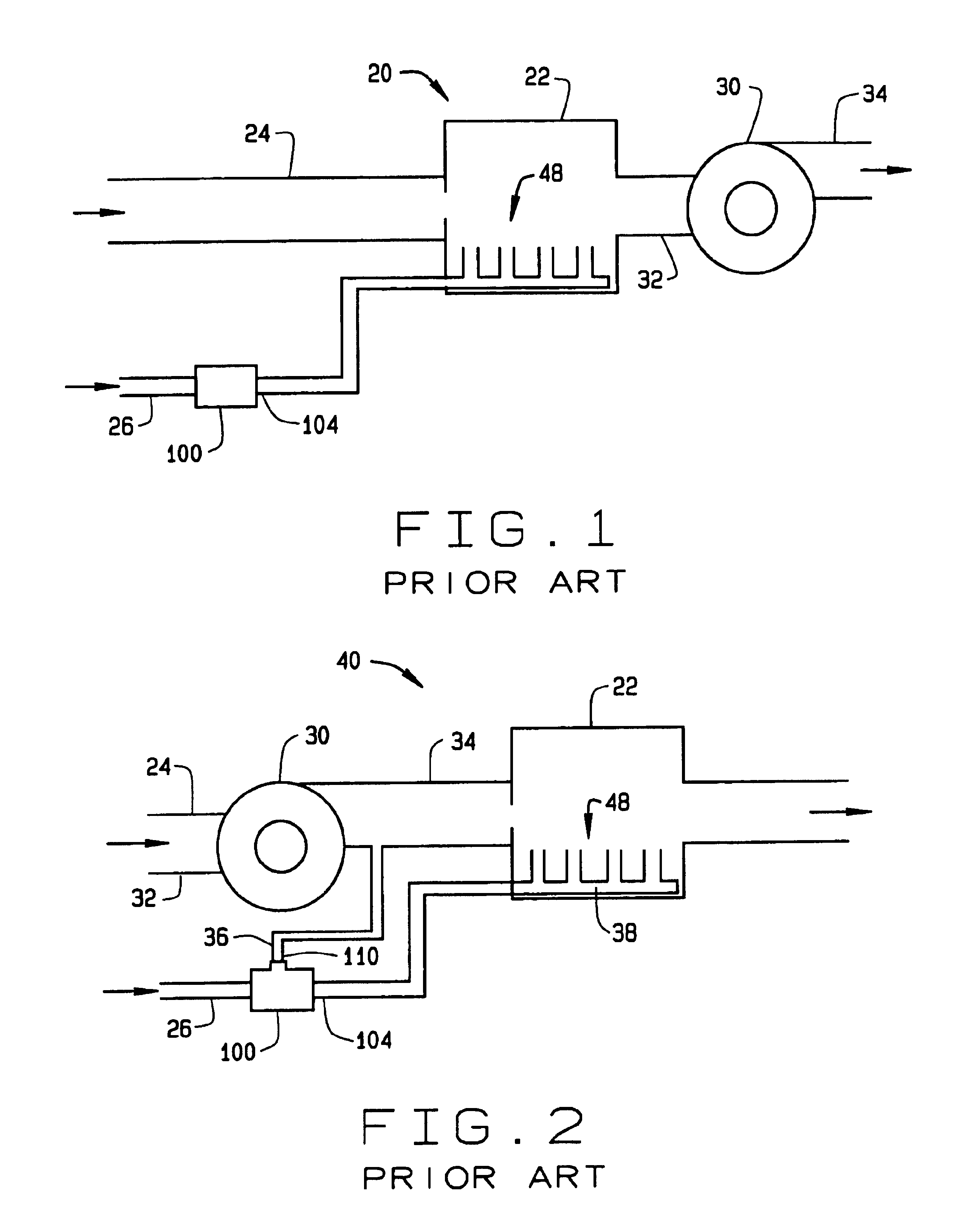
[0016]A conventional induced draft combustion system is indicated generally as 20 in FIG. 1. The combustion system 20 comprises a combustion chamber 22 having a burner 48 therein, an air inlet 24, and a gas inlet 26. A gas valve 100 in the gas inlet 26 controls the flow of gas to the burner. A blower 30, having an inlet 32 and an outlet 34 connected to the combustion chamber 22 draws the hot combustion gases from the combustion chamber to, for example, the heat exchanger of a residential furnace or commercial heater, thereby drawing air through the air inlet 24 into the combustion chamber. In a conventional system shown in FIG. 1, increasing the speed of the blower 30 increases the air flow to the combustion chamber 22, but it does not affect the flow of gas to the combustion chamber 22. Thus, changes to the blower speed change the air to fuel ratio. Additionally, increasing the speed of the blower 30 typically increases air flow to the combustion chamber 22 up to pressures of only ...


PUM


Abstract

An improved gas appliance having a burner, a gas valve through which the flow of combustion gas to the burner is controlled, and a motor driven blower that supplies combustion air to the burner. The improvement includes means for increasing gas flow through the gas valve as blower speed increases, and decreasing gas flow through the gas valve as blower speed decreases, based on a pressure signal generated independently of combustion air pressure. This improvement allows a constant ratio of gas to air to be maintained in the burner while a combustion flow rate varies dependent on the blower motor revolutions per minute. Thus input pressures of combustion can be controlled at low cost.

Description

FIELD OF THE INVENTION[0001]The present invention relates generally to gas appliances and, more particularly, to controls for gas input to gas appliances.BACKGROUND OF THE INVENTION[0002]Gas appliances typically include valves for controlling gas input to the appliance's burners. Gas control valves are used in induced draft systems and in forced draft systems with pressure-assist modulation (PAM) to deliver gas to be combined with air for combustion. It is desirable to control gas and air input pressures in order to achieve desired combustion rates in appliance burners. One method of controlling gas input pressure is to electronically modulate gas control valve output relative to the air input pressure, by using a pressure transducer. Such an approach, however, is expensive.SUMMARY OF THE INVENTION[0003]The present invention in one embodiment is an improved gas appliance having a burner, a gas valve through which the flow of combustion gas to the burner is controlled, and a motor dr...

Claims


Application Information

Patent Timeline
Patent Type & Authority Patents(United States)
IPC IPC(8): F23D14/60F23D14/46F23N1/02F23N1/06F23N1/00
CPCF23D14/60F23N1/02F23N1/06F23N2033/04F23N2033/08F23N2233/04F23N2233/08
Inventor FREDRICKS, THOMAS J.DONNELLY, DONALD E.SHOEMAKER, RUSSELL T.
Owner EMERSON ELECTRIC CO
Why Eureka
Try Eureka