
Battery power source device, method for controlling the same, and method for providing address

a power source device and battery pack technology, applied in secondary cell servicing/maintenance, cell components, instruments, etc., can solve the problems of battery pack systems a to f to be incompatible with other equivalent systems, reduce the power supply of the vehicle, and increase the cos

Inactive Publication Date: 2005-07-19
PANASONIC EV ENERGY CO LTD
View PDF15 Cites 76 Cited by
  • Summary
  • Abstract
  • Description
  • Claims
  • Application Information

AI Technical Summary

Benefits of technology

[0013]When the battery power source device is employed for supplying drive power to a vehicle, the load condition of a battery power source device varies all the time as the running condition of the vehicle varies. Consequently, the battery power source device has such a high power capacity as afford to meet the maximum power consumption requirement of the vehicle, and thus never causes a sudden drop in the powering performance of the vehicle due to the disconnection of the abnormal one of the battery pack blocks from the parallel or the serial parallel connection. Additionally, the vehicle requires the maximum service power only for a short period of time and the battery is able to withstand an excessive load condition for the short period of time. Accordingly, when an abnormal battery pack block is disconnected to thereby cause a drop in the maximum allowable load level, the battery is able to support a load power that exceeds the level, thereby preventing the abnormal state from having a detrimental effect on the entire battery power source device.
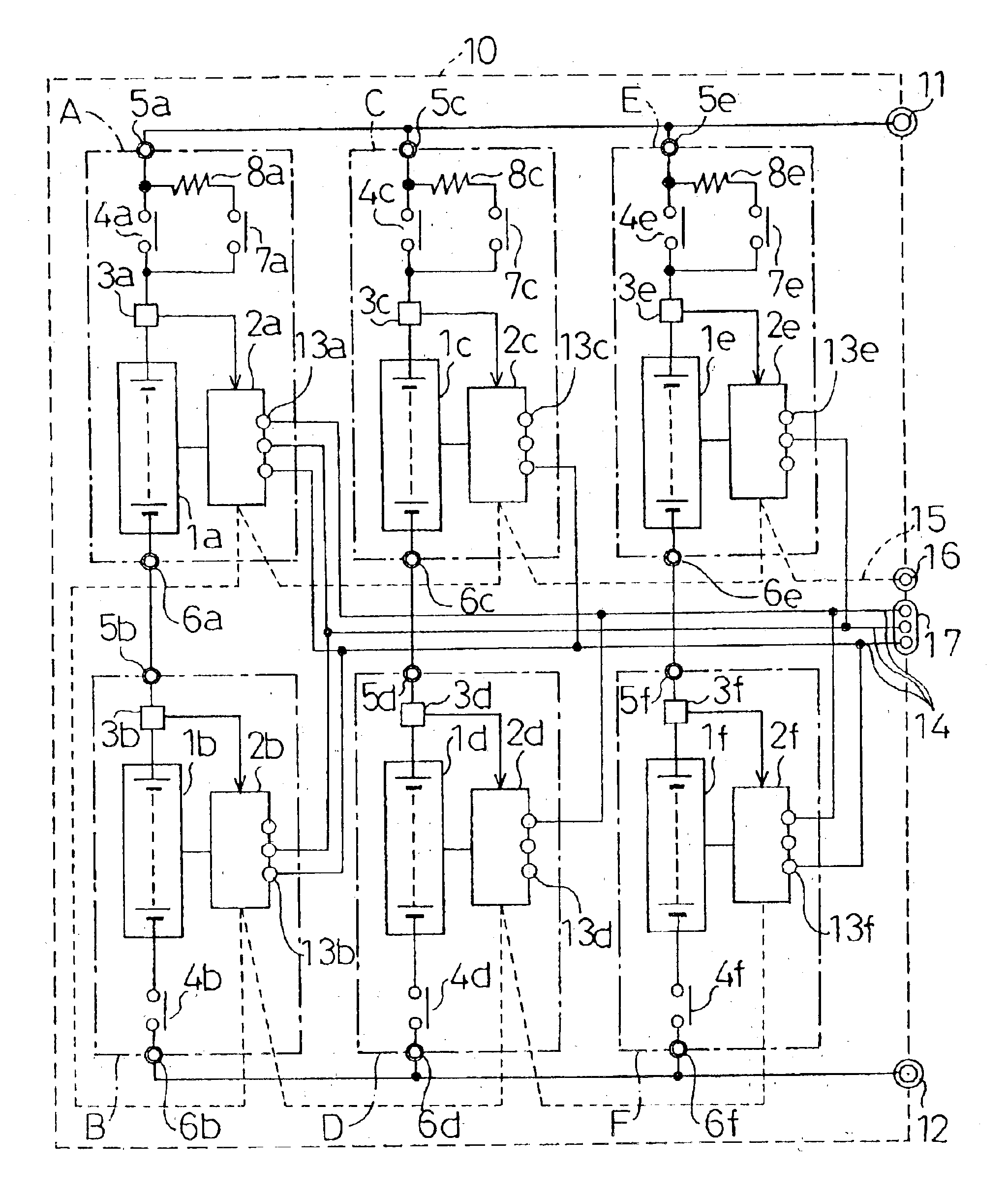
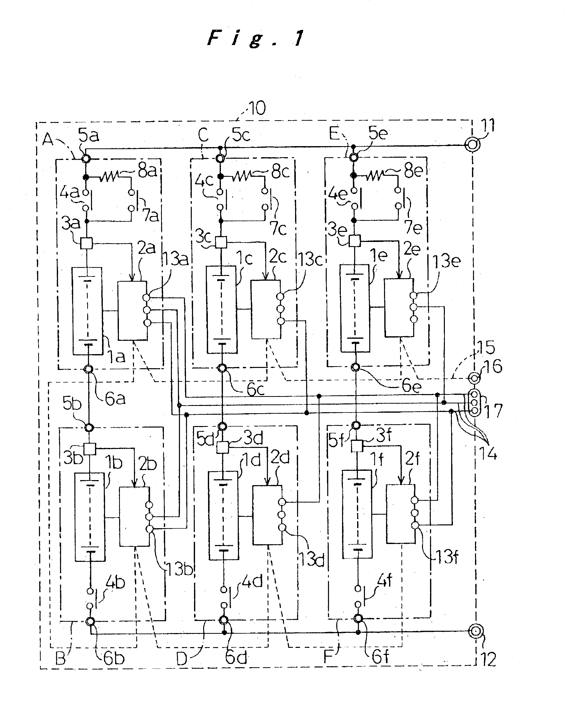
[0015]With a battery power source device configured to have a plurality of battery pack blocks, it is required that the battery ECUs each for controlling the operating condition of each of the battery pack blocks are connected to each other via a communication line, which is in turn connected to an external controller, to individually monitor the operating condition of each battery pack block. This necessitates setting an address to each battery ECU. Each battery ECU is provided with the address setting terminals the same in number as the bits corresponding to the number of the battery pack blocks. The address setting terminals are connected to the connection lines differently for each of the battery ECUs to set addresses to each of the battery pack blocks. This makes it possible to provide a common compatible specification to the battery ECUs to improve productivity and the ease of maintenance.
[0019]The battery ECUs each provided in their respective battery pack blocks can employ one battery ECU as a master and the other battery ECUs as slaves depending on the connection between the address setting terminals and the connection lines. The communication device allows the master battery ECU to collect the information on the operating condition of each of the slave battery ECUs, and the master battery ECU provides control to the entire battery power source device. The master battery ECU collects the information on the operating condition of each slave battery ECU and then transmits the information to outside, thereby allowing an external apparatus employing the battery power source device to monitor the operating condition of the power source device and provide control thereto.
[0020]The aforementioned arrangement can further have a function for setting, when an abnormal state is detected in the battery pack block controlled by the master battery ECU, one of the other battery pack blocks, the one being connected in parallel to the abnormal battery pack block, to serve as a master battery ECU, and for disconnecting thereafter the abnormal battery pack block from the parallel connection. When an abnormal state is detected in the battery pack block controlled by the master battery ECU, the master setting can be set to another battery ECU to thereby disconnect the abnormal battery pack block from the parallel connection. This allows the output voltage of the battery power source device to remain unchanged and the master battery ECU to provide control to the entire battery power source device, thereby never causing an abnormal state of one battery pack block to stop the operation of the battery power source device.

Problems solved by technology

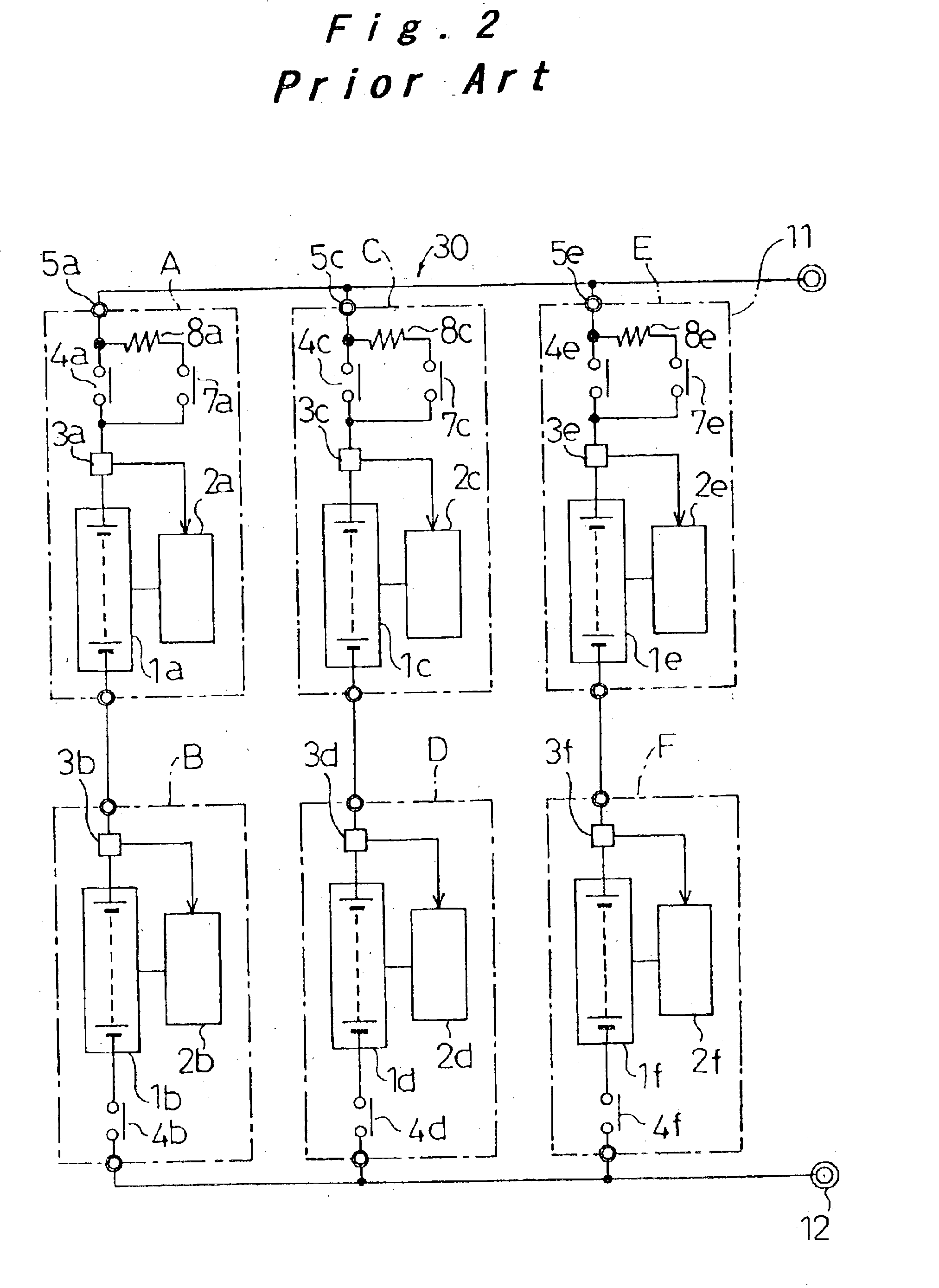
With the battery power source device 30 including a plurality of battery pack systems A to F, there is a problem that any failure of one battery pack block have detrimental effects on the entire battery power source device, resulting in a decreased power supply to the vehicle.
In general, an address number is stored in a memory to, set the address; however, this memory storing individual address numbers can result in an increase in cost and cause the battery pack systems A to F to be incompatible with other equivalent systems.

Method used


Image

  • Battery power source device, method for controlling the same, and method for providing address
  • Battery power source device, method for controlling the same, and method for providing address
  • Battery power source device, method for controlling the same, and method for providing address

Examples


Embodiment Construction

[0024]Now, the present invention will be described below in more detail with reference to the accompanying drawings in accordance with the embodiment to further the understanding of the invention. The embodiment described below is an example implementation of the present invention and not intended to limit the technical scope of the invention. The same components as the prior art components are indicated with the same reference numerals and symbols.

[0025]This embodiment relates to a battery power source device that is employed as a power source for driving a hybrid vehicle, especially a large hybrid vehicle, which incorporates a motor and an engine. As shown in FIG. 1, to meet a high power load demanded by the large hybrid vehicle, a battery power source device 10 according to this embodiment includes six battery pack blocks 1a to 1f in which the battery pack blocks 1a and 1b, the battery pack blocks 1c and 1d, and the battery pack blocks 1e and 1f are connected in series, respectiv...


PUM

PropertyMeasurementUnit
drive poweraaaaaaaaaa
currentaaaaaaaaaa
temperatureaaaaaaaaaa

Abstract

A method for controlling and addressing a battery power source device having a plurality of battery pack systems connected in parallel or serially in parallel, each battery pack system having a battery pack block and a battery ECU connected thereto, is provided. The battery ECUs are connected to each other over communication lines, and a plurality of address setting terminals and address lines are connected to each other differently to provide a unique address to each battery ECU. When an abnormal state is detected in one of the battery pack blocks over the communication line, control is provided to the abnormal one of the battery pack blocks, identified by its address, to turn off its open / close relay contact to disconnect it from the parallel or the serial parallel connection, thereby preventing the function of the entire battery power source device from being stopped or degraded.

Description

[0001]The present disclosure relates to subject matter contained in priority Japanese Patent Application No. 2002-3141, filed on Jan. 10, 2002, the contents of which is herein expressly incorporated by reference in its entirety.BACKGROUND OF THE INVENTION[0002]1. Field of the Invention[0003]The present invention relates to a battery power source device for supplying high drive power required for large hybrid vehicles, a method for controlling the power source device, and a method for assigning an address.[0004]2. Description of Related Art[0005]A battery power source device employed as a power source for hybrid vehicles includes a battery pack block having a plurality of battery modules (e.g., 30 battery modules) connected in series, each battery module having a plurality of rechargeable batteries (e.g., 6 batteries) connected in series. To provide control to the operating conditions of the battery pack block, the battery power source device further includes a battery ECU (Electroni...

Claims


Application Information

Patent Timeline
Patent Type & Authority Patents(United States)
IPC IPC(8): G01R31/36H02J13/00H02J7/00H01M10/42
CPCG01R31/3658H01M10/441H01M10/482H01M10/488G01R31/396Y02E60/10
Inventor KAWAI, HIROKAZUKADONO, MASAHIRO
Owner PANASONIC EV ENERGY CO LTD
Learn More