Clock down sensor

a technology of clock down and sensor, applied in the direction of generating/distributing signals, pulse techniques, instruments, etc., can solve the problems of time and transmission resource was

Inactive Publication Date: 2005-07-19
ASIA OPTICAL INT LTD
View PDF6 Cites 0 Cited by
  • Summary
  • Abstract
  • Description
  • Claims
  • Application Information

AI Technical Summary

Benefits of technology

[0005]The main object of the present invention is to provide an apparatus used to monitor whether clock pulse signals exist in a transmission media and to yield a detecting signal taken as a warning. Thereby, the phenomena of a transmission termination can be detected earlier, and the transmission can be recovered in time.

Problems solved by technology

Thus, time and transmission resource wastes are caused because it is unable to be detected and repaired immediately.

Method used


Image

  • Clock down sensor
  • Clock down sensor
  • Clock down sensor

Examples


Embodiment Construction

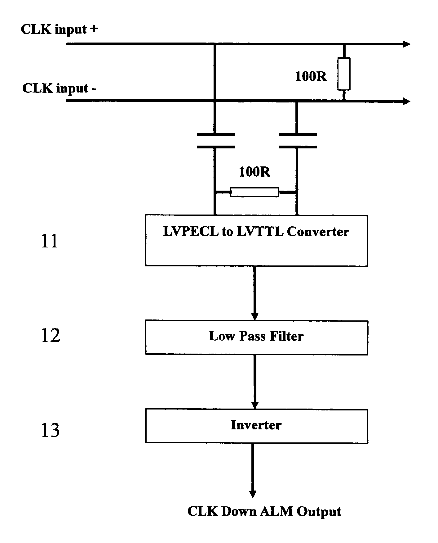
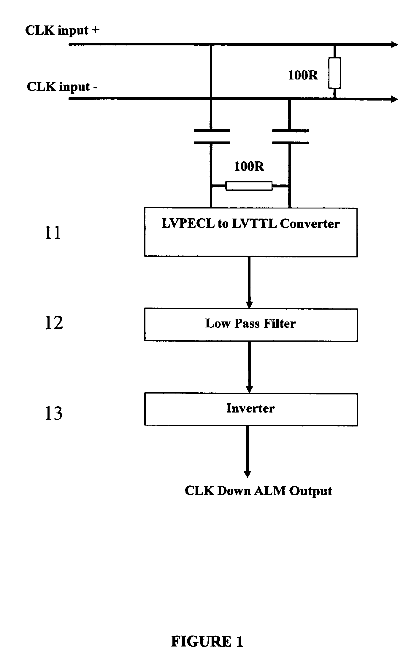
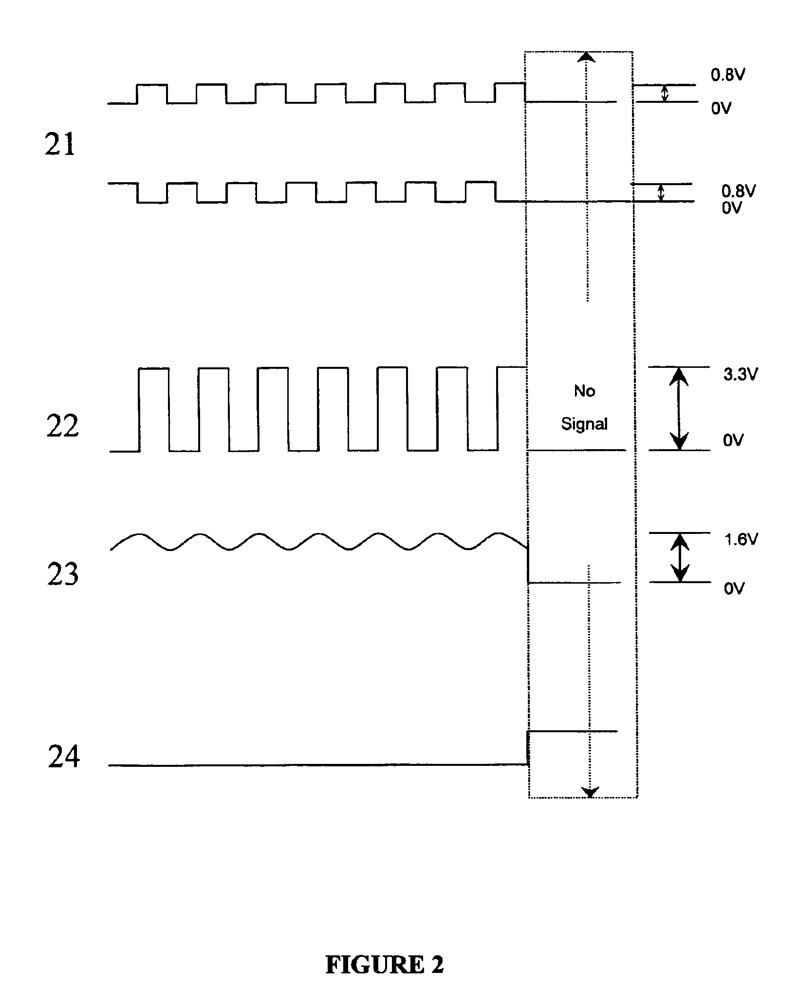
[0014]First, please refer to FIG. 1 and FIG. 2. FIG. 1 is a circuit block diagram showing a circuit of a clock down sensor according to one embodiment of the present invention, and FIG. 2 is a signal waveform diagram corresponding to every circuit block generated from the clock down sensor shown in FIG. 1.

[0015]According to the present invention, a positive and a negative clock pulse signals are first connected to a LVPECL (Low Voltage Positive Emitter Coupling Logic) to LVTTL (Low Voltage Transistor Transistor Logic) converter (11) through capacitors C1 (CLK input+) and C2 (CLK input−); the clock pulse signal is converted from an original positive and negative PECL square pulse signal of 0.8 V (21) to a TTL square pulse signal of 3.3V (22). Next, a signal with a DC level at an approximate potential 1.6V (23) is obtained through a low-pass filter (12). Finally, the DC level signal is inverted to a detecting signal (24) by way of an inverter (13).

[0016]How to obtain the detecting sig...


PUM


Abstract

A clock down sensor mainly comprises a converter and a low-pass filter. The converter is used to convert an input signal from a PECL (Positive Emitter Coupling Logic) signal to a TTL (Transistor Transistor Logic) signal, the low pass filter is used to obtain a DC (Direct Current) level of the TTL signal. Thereby, the sensor can judge whether the clock signal is terminated according to the potential of the output signal in order to emit a warning so that a breakdown elimination inquiry can be done or automatic breakdown elimination can be processed earlier.

Description

BACKGROUND OF THE INVENTION[0001]1. Field of the Invention[0002]The present invention relates to a clock down sensor, and more particularly to a clock down sensor used to monitor the transmission status of network.[0003]2. Description of Related Art[0004]At present, there are many types of signal sensors and so are their usages; they can generally be used on fire warning, guarding against burglar and measurement. The basic principle of theirs is to use a temperature, pressure or light sensing equipment to detect the change of temperature, pressure and light, and then, a detecting signal is emitted to use as a warning signal. In general, clock pulse signal detection function does not exist in a general transmission facility, therefore, when a data transmission is processed in an optical fiber or a general wire material, if disappearance of a pulse signal happens in the middle of the transmission due to oscillator or other elements failure, no warning is received in the system even if...

Claims


Application Information

Patent Timeline
Patent Type & Authority Patents(United States)
IPC IPC(8): H03K5/19G06F1/04
CPCG06F1/04H03K5/19
Inventor YANG, CHANG YI
Owner ASIA OPTICAL INT LTD
Why Eureka
Try Eureka