Position detection method and device
- Summary
- Abstract
- Description
- Claims
- Application Information
AI Technical Summary
Benefits of technology
Problems solved by technology
Method used
Image
Examples
Embodiment Construction
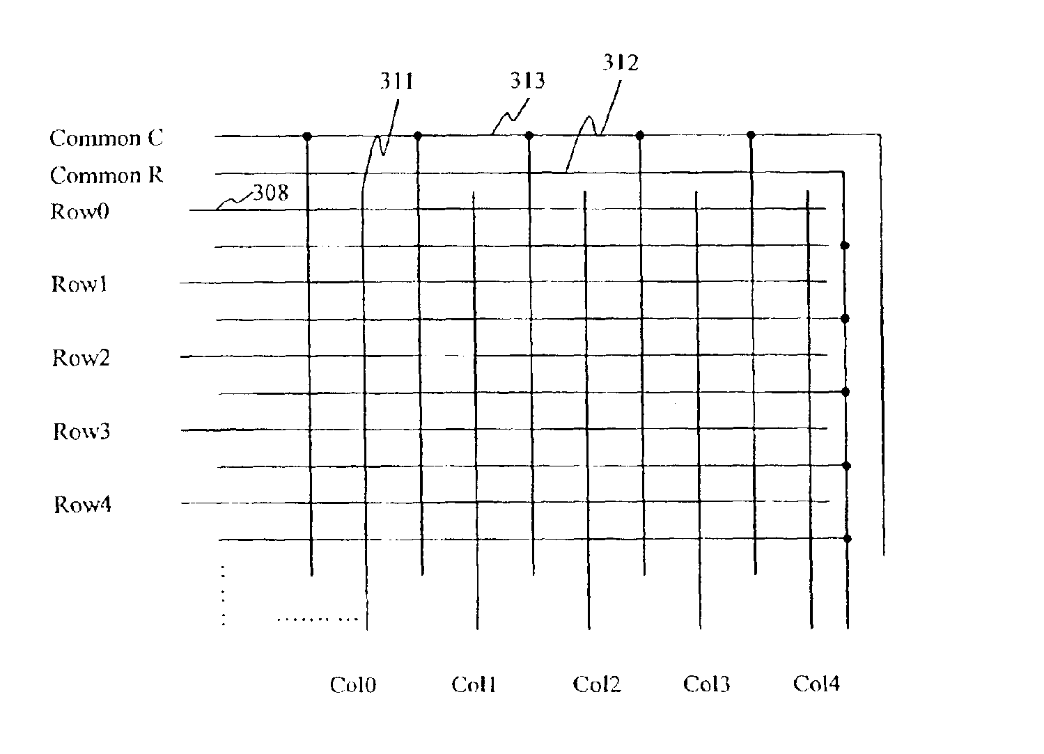
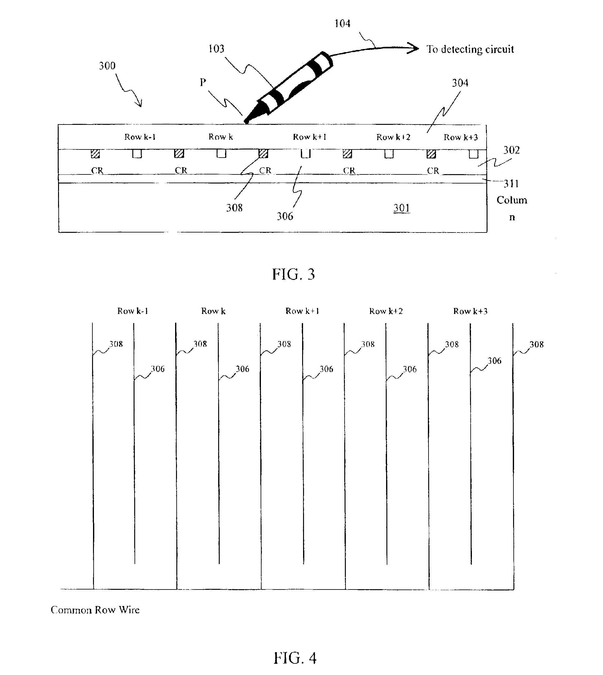
[0028]The cross sectional view of a conductive wire board is shown in FIG. 3 and the layout of the row conductive wires and the common of row wires is shown in FIG. 4 according to one embodiment of the present invention. Referring to FIG. 3, the conductive wire board 300 for position detection is made by screen printing, deposition or plating of conductive layer of the column wire on a substrate 301, the conductive layer such as aluminum or copper is then patterned and etched (for deposition method) to form the column wire from column 0 to column M 311 and the common column wire. After forming an insulating layer 302, another conductive layer is formed on the insulating layer 302 using the same method to form the row wire from row 0 to row N 306, and the common row wire CR 308. Finally a layer of insulating film 304 is formed on the top of the row and common row wires.
[0029]A point P is detected by a capacitive coupling device 103, which is connected to an amplifier (shown in FIG. 1...
PUM
 Abstract
Description
Claims
Application Information
 - R&D
- Intellectual Property
- Life Sciences
- Materials
- Tech Scout
- Unparalleled Data Quality
- Higher Quality Content
- 60% Fewer Hallucinations
Browse by: Latest US Patents, China's latest patents, Technical Efficacy Thesaurus, Application Domain, Technology Topic, Popular Technical Reports.
© 2025 PatSnap. All rights reserved.Legal|Privacy policy|Modern Slavery Act Transparency Statement|Sitemap|About US| Contact US: help@patsnap.com


