Relief smoothing apparatus, fixing device, and image forming apparatus

a technology of fixing device and smoothing apparatus, which is applied in the direction of electrographic process apparatus, instruments, optics, etc., can solve the problems of uneven glossy appearance, inability to obtain smooth image quality, and diffuse incident illumination light, so as to prevent blistering and eliminate the appearance of a step-like toner image

Inactive Publication Date: 2005-07-19
FUJIFILM BUSINESS INNOVATION CORP +1
View PDF10 Cites 13 Cited by
  • Summary
  • Abstract
  • Description
  • Claims
  • Application Information

AI Technical Summary

Benefits of technology

[0009]The present invention has been made in view of the above technical problems and provides a fixing device enabling both elimination of a step-like appearance of a toner im...

Problems solved by technology

On a color image surface after the fixing process by the roll fixing device, unevennesses are formed with a size of about 10 to 100 μm, for example, because of a difference in thickness between toner layers, which leads to occurrence of an uneven glossy.
As a result, the color image formed on the plain paper or the coat paper such as the general printing paper makes an incident illumination light diffuse and appears poor in glossiness when visually observed.
Meanwhile, th...

Method used


Image

  • Relief smoothing apparatus, fixing device, and image forming apparatus
  • Relief smoothing apparatus, fixing device, and image forming apparatus
  • Relief smoothing apparatus, fixing device, and image forming apparatus

Examples


experiment 1

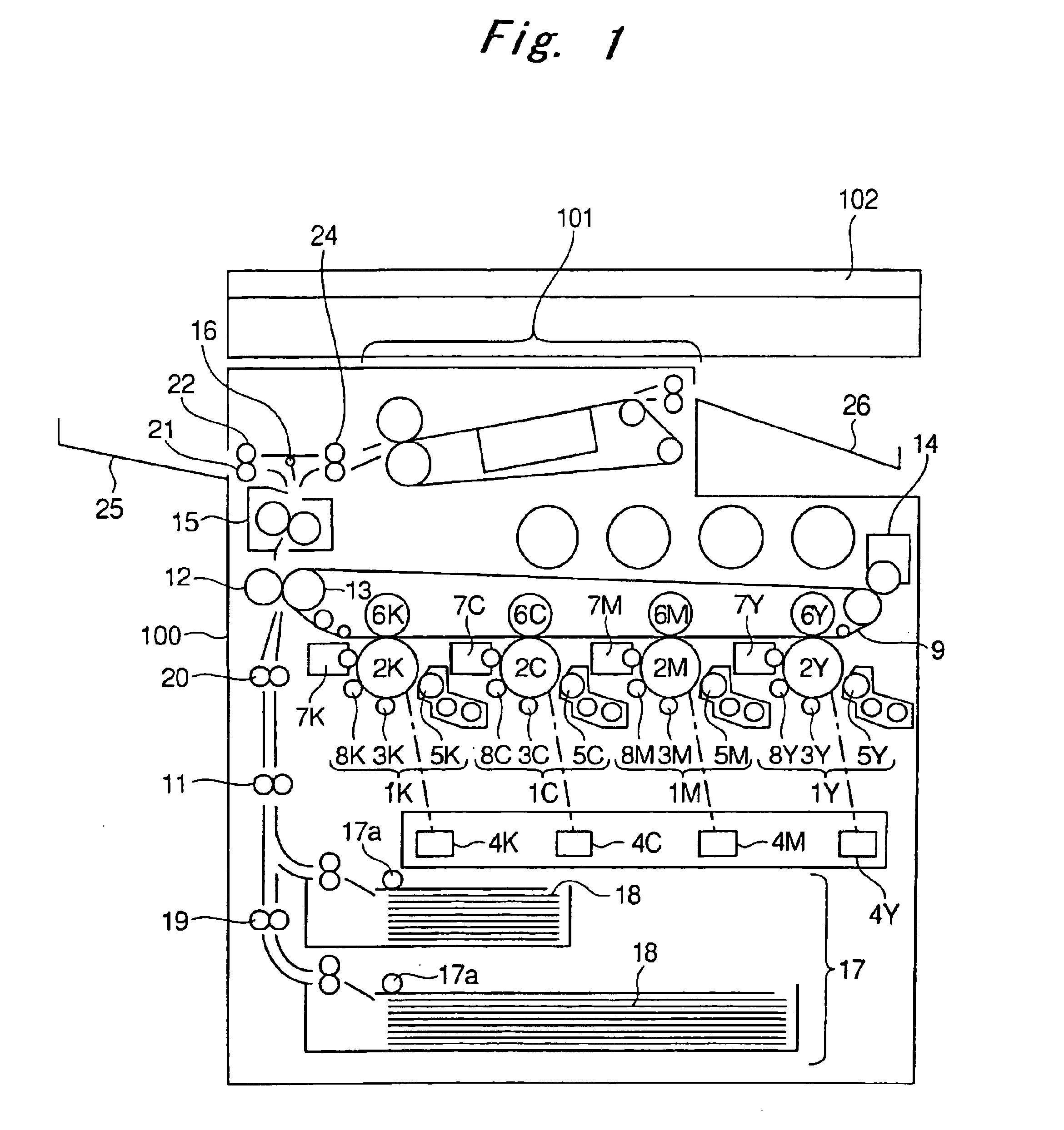
[0079]In the image forming apparatus 100 thus structured, the following experiment was performed for specifying appropriate temperatures of the heat fixing roll 40 and the pressure roll 42 and a heating member temperature Tn.

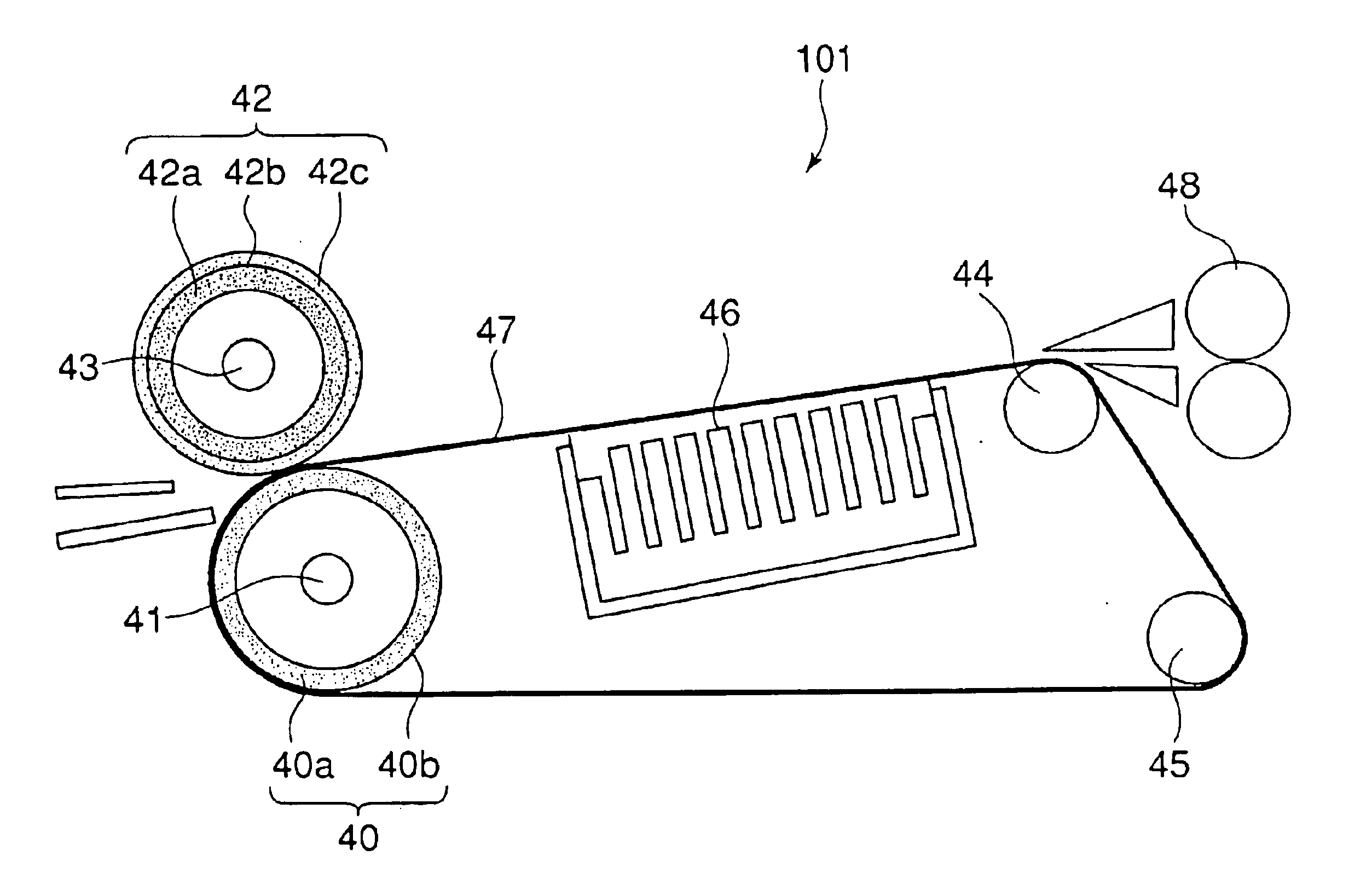
[0080]First, experimental conditions are described. With regard to a more detailed structure of the second fixing device 102, the heat fixing roll 40 is structured as an aluminum hard roll having a diameter φ of 50 mm and the pressure roll 42 is structured as an elastic roll having a diameter φ of 50 mm (rubber layer: 2 mm). Also, a width (nip width) of the nip portion formed between the heat fixing roll 40 and the pressure roll 42 (to be specific, the nip portion between the fixing belt 47 and the pressure roll 42) in the transport direction is 6.0 mm. Also, a nip pressure is 1.5 MPa. Further, adopted as the fixing belt 47 is one having a polyimide base material with a thickness of 75 μm coated with the silicone rubber layer having a thickness of 35 μm. Also, t...

experiment 2

[0085]Next, in the image forming apparatus 100 thus structured, the following experiment was performed for specifying an appropriate nip pressure P generated between the heat fixing roll 40 and the pressure roll 42 and time t required for the sheet to pass through the nip portion. The experimental condition and method are almost the same as in Experiment 1.

[0086]FIG. 11 and FIG. 12 are graphs illustrating the experimental results in the case where the nip pressure P is 0.5 MPa and the nip time t is 0.05 sec and where the nip pressure P is 1.5 MPa and the nip time t is 0.5 sec, respectively. The vertical axis represents the relief size and the horizontal axis represents the heating member temperature Tn in each graph.

[0087]From those experimental results, the nip pressure and the time required for the sheet to pass through the nip portion preferably meet the following relationships: 0.50≧P·t [MPa·s]≧0.1, P≧1.0 [MPa], and t≧0.1 [s] (P: nip pressure and t: time required for the sheet t...


PUM


Abstract

To provide an relief smoothing apparatus that smoothes an image on a recording sheet which is obtained by forming a polyolefin resin coating layer on a base sheet and forming a receiving layer, in which a toner image is infiltrated, on the base sheet, including: plural tension rolls including a first roll; an endless; a second roll; and a heating source, the recording sheet, in which provided that a surface temperature of the first roll is represented by Tn [° C.], a Vicat softening temperature of the polyolefin resin is represented by Tv [° C.], and a time required for the recording sheet to pass through the nip portion is represented by t [sec], the following relationship is established: (Tv+55)×(1+{fraction (1/100)} t)≧Tn≧(Tv+20)/(1+{fraction (1/100)} t) [° C.].

Description

FIELD OF THE INVENTION AND RELATED ART STATEMENT[0001]The present invention relates to a fixing device of an image forming apparatus adopting an electrophotographic system and an electrostatic transfer system, for example, a copying machine, a printer, a facsimile machine, and a multi-function machine thereof. In particular, the present invention relates to an improvement in a belt type fixing device.[0002]Up to now, as a color image forming apparatus adopting an electrophotographic system, such as a color copying machine or a color printer, there is one having only one photosensitive drum on which toner images in respective colors of yellow (Y), magenta (M), cyan (C), and black (BK) are formed in order. The toner images in the respective colors of yellow (Y), magenta (M), cyan (C), and black (BK) formed in order on the photosensitive drum are multiply transferred onto a recording sheet, following heating the toner images and fixing the images onto the recording sheet to thereby for...

Claims


Application Information

Patent Timeline
IPC IPC(8): G03G15/20G03G7/00G03G21/00G03G15/16
CPCG03G15/2064
Inventor KANESAWA, YOSHIOMURAI, ASHITA
Owner FUJIFILM BUSINESS INNOVATION CORP
Why Eureka
Try Eureka