Constant force actuator

a constant force actuator and actuator technology, applied in the direction of surveying, drilling pipes, borehole/well accessories, etc., can solve the problems of affecting the motion of tools along the well, and affecting the accuracy of the tool. achieve the effect of constant input axial for

Inactive Publication Date: 2005-07-26
SCHLUMBERGER TECH CORP
View PDF11 Cites 92 Cited by
  • Summary
  • Abstract
  • Description
  • Claims
  • Application Information

AI Technical Summary

Benefits of technology

[0021]Briefly, the present invention is a mechanism that uses a force applied in a first linear direction to lift or support a load, or transmit a force, in a second linear direction that is substantially perpendicular to the first linear direction. Devices and mechanisms constructed in accordance with the principles of the present invention are constructed in such manner that the force that is required to support the load is of practically constant magnitude and is independent of the position of the load in the second linear direction. In particular, the invention relates to logging tools or other devices for wells that are conveyed along the inside surfaces of a wellbore or a pipe, or between spaced surfaces. The invention can conveniently take the form of a centralizer, a caliper, an anchoring device, or a tractor mechanism for use in wells, or may take the form of a lifting or load supporting device when embodied in jacks and other lifting or load supporting devices. The function of the present invention is to apply or react radial forces against the internal cylindrical wall of a wellbore or circular conduit, such as a pipe, for centralizing objects within the wellbore or pipe, to provide an anchoring function, or to provide mechanical resistance enabling the efficient operation of internal traction devices for conveying objects such as logging tools. When used as a centralizer for logging tools, a plurality of radially movable actuating linkages embodying the present invention maintain the logging tools at the center of the wellbore and thus enhance the accuracy of the logging process. When used as a caliper, the invention extends arms or other linkages toward the wellbore wall and exerts a controlled radial force on the wall surface. When used as an anchoring device, the invention can apply or react radial forces that generate enough friction against a wellbore or pipe wall to prevent any sliding at the points of contact between the anchoring device and the wall surface of the wellbore or pipe. The latter is needed for the construction and operation of downhole tractor tools, which are often used to convey other tools along wells that have horizontal or highly deviated sections. A major advantage of the present invention is that the magnitudes of the radial forces that it applies to the wellbore wall are virtually constant and independent of the wellbore size.
[0022]The main elements of the invention are force transmitting members or hubs, wheels, axles, and at least a pair of linkage arms with built-in wedges or with guide surfaces of predetermined geometry defined by the linkage arms. For purposes of the present invention the terms “force transmitting members” or “hubs” are each intended to mean members of any desired configuration, that are relatively linearly movable, with one or both of the members movable and, if desired, one of the members stationary. The linkage arms, the force transmitting members or hubs, and the wheels are joined by the axles to form a linkage that can expand or contract radially as the distance between the hubs changes in the axial direction. The linkage arms are joined together by a pivot member or axle at one of their ends, which allows only angular motion of the linkage arms to occur. At their second ends, the linkage arms are attached to separate hubs by axles or pivots that can both rotate and slide within an elongate slot in the hub body. The wheels or rollers, which define movement control elements, are rotatably mounted onto the hubs and, when in contact with the guide surfaces of the linkage arms, roll on the force transmitting guide surfaces of wedges or guide surfaces that are built into the linkage arms, formed on the linkage arms, or attached to the linkage arms. Although wheels or rollers are shown as force transmitting elements of the hubs or force transmitting members, structures other than wheels or rollers may be employed within the spirit and scope of the present invention to transmit forces from the hubs to the guide surfaces of the wedges or linkage arms. The force transmitting guide surfaces are of predetermined geometry so as to react with the force transmitting surfaces of the wheels or rollers and develop resultant force vectors on the linkage arms that are angulated with respect to the direction of linear motion of one or both of the hubs. These angulated force vectors cause pivotal movement of the linkage arms even when the linkages are fully retracted. This feature permits ease of starting motion of the linkages from their retracted positions.
[0023]The invention combines two separate principles to generate the required radial expansion. At small angles between the arms and the hubs, the radial force is created by the wheels, which roll on the force transmitting surfaces of the wedges or linkage arms. At larger angles, the expansion movement of the linkages is created on the principle of a triangular three-bar linkage. A transition between the two principles occurs at a pre-selected intermediate angle of the linkage arms between the fully retracted and fully extended positions. By combining these two principles and by the selection, placement and shape of the force transmitting guide surfaces of the wedge members it is possible to achieve substantially constant input axial force, which is the major advantage of the present invention and which is distinct as compared with other similar devices.

Problems solved by technology

In addition, the centralizing force and the frictional drag resulting from it are such a small fraction of the total tension on the logging cable that its variability can be neglected for all practical purposes.
Wells that have horizontal or highly deviated sections may, however, present problems.
On the other hand, in a different wellbore size, the force exerted by the centralizer may be excessive, causing extra frictional drag that impairs the motion of the tools along the well.
This requirement is sometimes difficult to achieve in horizontal sections of the well and variable wellbore sizes.
This usually leads to poor efficiency of the mechanical device and its under-utilization in a large range of wellbore sizes.
Horizontal and highly deviated wells present yet another problem.
Logging tools cannot be effectively conveyed into such wells by the force of gravity.
Like centralizers, they also have the problem of radial force variability as a function of wellbore size.
However, no satisfactory solution to this problem has thusfar been disclosed.
These mechanisms must, however, be replaced at the surface, which is very inconvenient.
In addition, some wells are drilled with a variety of wellbore sizes that no single mechanism can handle.
While passive constant force mechanisms are commercially available, no active constant force mechanism has been disclosed.
The disadvantage is that it can only be used for centralizers, but not for calipers and anchoring devices that require selective opening and closing of the arms.
Another disadvantage is that this operating principle requires the centralizer to be quite long, which may be undesirable in some instances.
The disadvantage of this approach is that it does not solve the problem completely, as the radial force still varies with the wellbore size.
It also makes construction of the device difficult, especially when it is desirable to use more than two centralizing arms.
A major disadvantage is the relatively limited range of radial expansion.

Method used


Image

  • Constant force actuator
  • Constant force actuator
  • Constant force actuator

Examples


Embodiment Construction

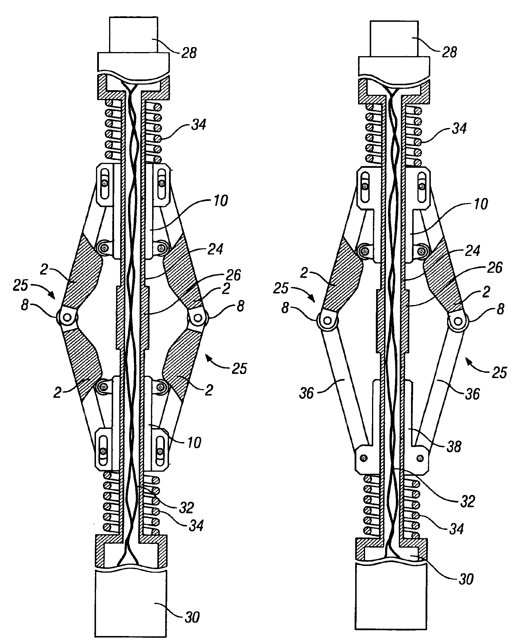
[0039]Illustrative embodiments of the invention are described below. It will be appreciated that in the development of any such actual embodiment, numerous implementation-specific decisions must be made to achieve the developer's specific goals, such as compliance with system-related and business-related constraints, which will vary from one implementation to another. Moreover, it will be appreciated that such a development effort might be complex and time consuming but would nevertheless be a routine undertaking for those of ordinary skill in the art having the benefit of this disclosure.

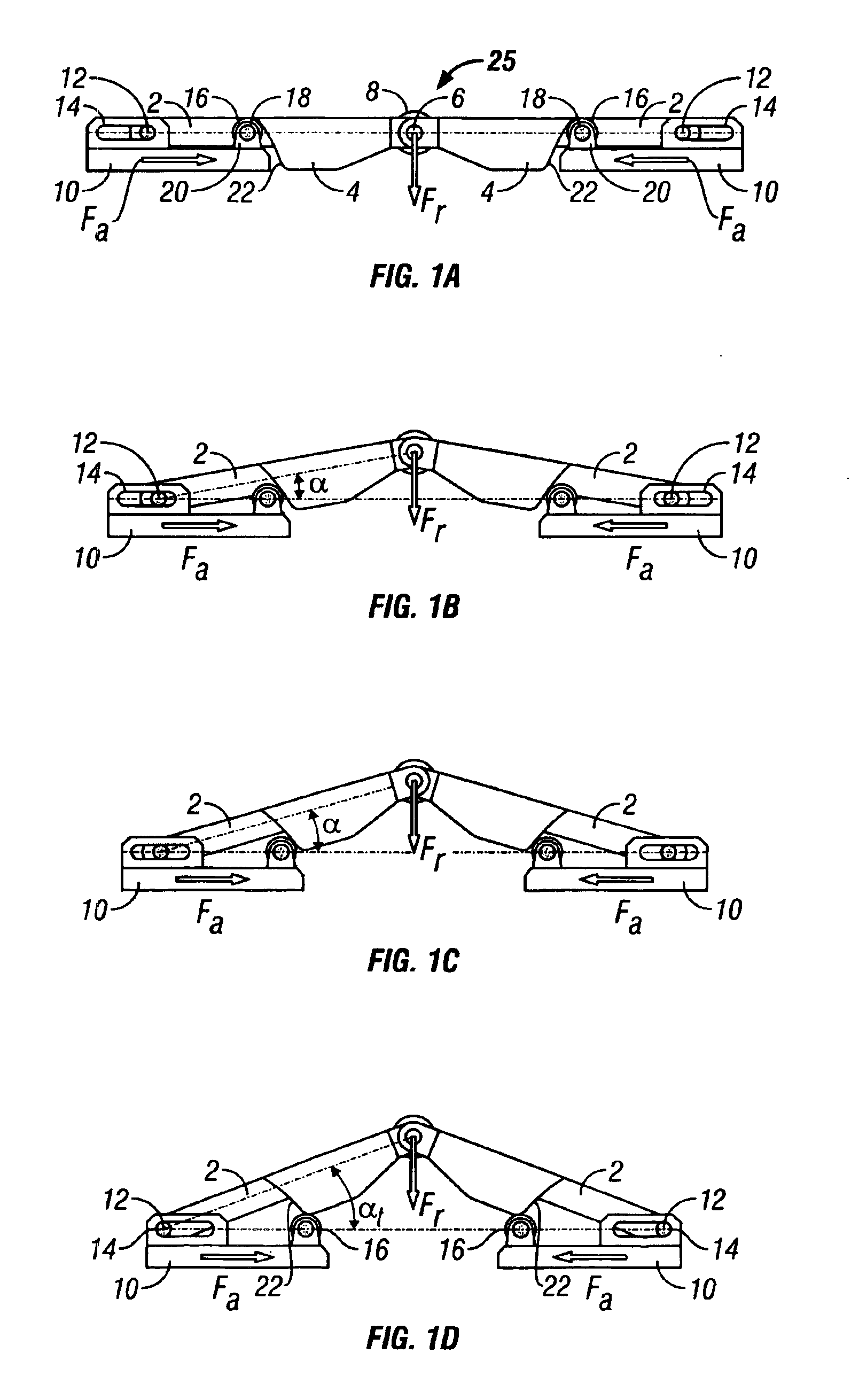
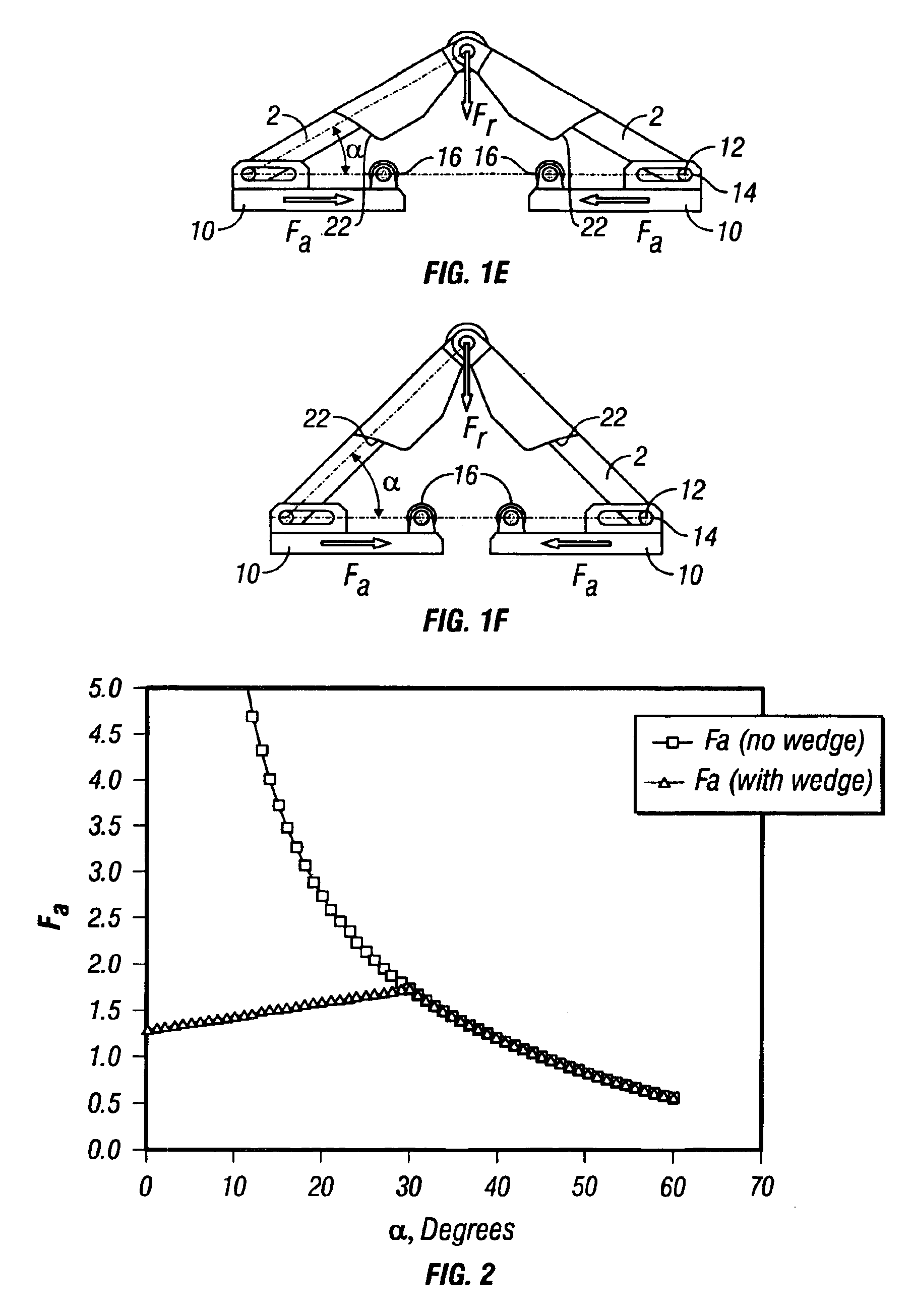
[0040]Referring now to FIGS. 1A-1F, the basic principles of the present invention are shown by way of operational illustrations, with the substantially constant force linkage of the apparatus being shown in its closed or fully retracted condition in FIG. 1A and at various stages of movement to a fully open or fully extended condition shown in FIG. 1F. The major elements and the principle of operati...


PUM


Abstract

A substantially constant force actuator that is applicable to centralizers, anchors and tractors for use in wells and is applicable to lifting devices such as jacks and load supporting devices. One or more sets of linkage arms are angularly movable by the force of one or more force transmitting members from a minimum angle with the force transmitting members at maximum spacing to a maximum angle with the force transmitting members at minimum spacing to impart a substantially constant force to an object or surface, with the direction of the force being substantially perpendicular to the direction of relative linear movement of the force transmitting members. With the linkage arms at their minimum angles, movement control elements on at least one of the force transmitting members react with guide surfaces of the linkage arms to achieve angular linkage movement and to develop a substantially constant force during angular linkage movement.

Description

CROSS-REFERENCE TO RELATED APPLICATIONS[0001]This application claims priority from U.S. Provisional Application No. 60 / 364,189, filed Mar. 13, 2002, which is incorporated herein by reference.BACKGROUND OF THE INVENTION[0002]1. Field of the Invention[0003]The present invention relates to mechanisms that employ a force applied in one direction to lift or support a load in a direction perpendicular to the direction of the applied force. Such mechanisms find application in many fields and may be employed, for example, in tools for use in wells or pipes, such as centralizers, calipers, anchoring devices, and tractors. The invention is particularly applicable to the field of tractors for conveying logging and service tools in deviated or horizontal oil and gas wells, or in pipelines, where such tools may not be readily conveyed by the force of gravity. The invention may also be employed in jacking devices.[0004]2. Description of Related Art[0005]After an oil or gas well is drilled, it is ...

Claims


Application Information

Patent Timeline
Patent Type & Authority Patents(United States)
IPC IPC(8): E21B17/00E21B17/10E21B23/04E21B23/01E21B23/00E21B47/08E21B47/00B66F3/12B66F3/22E21B4/18
CPCB66F3/12B66F3/22E21B4/18E21B17/1021E21B23/01E21B47/08E21B2023/008E21B23/001
Inventor SHEIRETOV, TODOR K.POST, ROGER A.ROY, CARL J.CORDERA, JOSEPH F.
Owner SCHLUMBERGER TECH CORP
Why Eureka
Try Eureka