
Cargo extension apparatus for motor vehicle

a technology for extending the carrying capacity of a motor vehicle and a carrying device, which is applied in the directions of transportation and packaging, loading/unloading vehicle arrangment, transportation items, etc. it can solve the problems of limiting the amount of load carrying capacity provided by the device or the literature, and affecting the truck's ability to haul large loads. , to achieve the effect of expanding the load carrying capacity

Inactive Publication Date: 2005-07-26
ERVIN DAVID R
View PDF9 Cites 39 Cited by
  • Summary
  • Abstract
  • Description
  • Claims
  • Application Information

AI Technical Summary

Benefits of technology

"The invention provides a platform for trucks, vans, and SUVs that can be positioned to the level of the wheel well to support the load being carried. The platform has a wide portion and narrow portion that lies on the bottom of the bed with the narrow portion nested between the wheel well and providing a camming arrangement to synchronously slide and raise the platform so that it is level with the top surface of the wheel well. The platform can also include foldable links or a foldable frame for supporting the platform in the deployed position. The technical effects of this invention include improved load carrying capacity and stability, as well as more efficient use of space in the bed of the vehicle."

Problems solved by technology

Obviously, this has an adverse affect on the truck's ability to haul large loads, as for example, sheets of sheet rock, ply wood, etc that measures say, 4′×8′.
One of the problems is that the devices provided heretofore or described in the literature are limited to the amount of load carrying capacity they can provide.
Also, since it is abundantly important that the center of gravity of the load is not situated where the load can tip, the structure must be such that the center of gravity is such that the load does not become dislodged from the bed or that the air current does not get under the load and dislodge it which, obviously, could lead to disastrous results.

Method used


Image

  • Cargo extension apparatus for motor vehicle
  • Cargo extension apparatus for motor vehicle
  • Cargo extension apparatus for motor vehicle

Examples


Embodiment Construction

[0025]As will become obvious from the description of the preferred embodiments of this invention, there are numerous way in which to execute this invention. Suffice it to say that the invention is essentially a load carrying structure that includes the wheel well of the vehicle as part of the load carrying structure and by the nature of the invention the width of the truck bed or SUV is not limited by the space between the wheel wells.

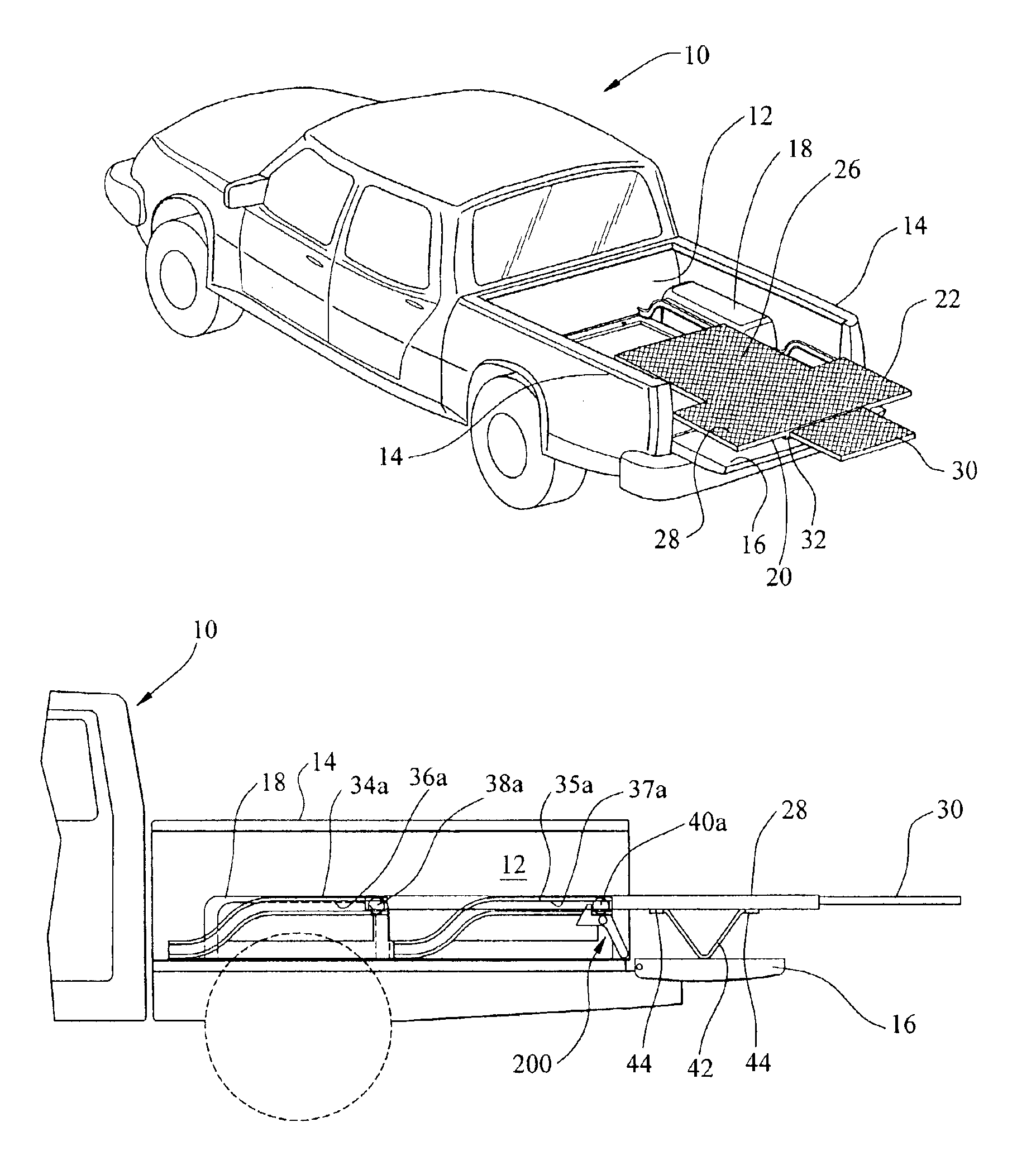
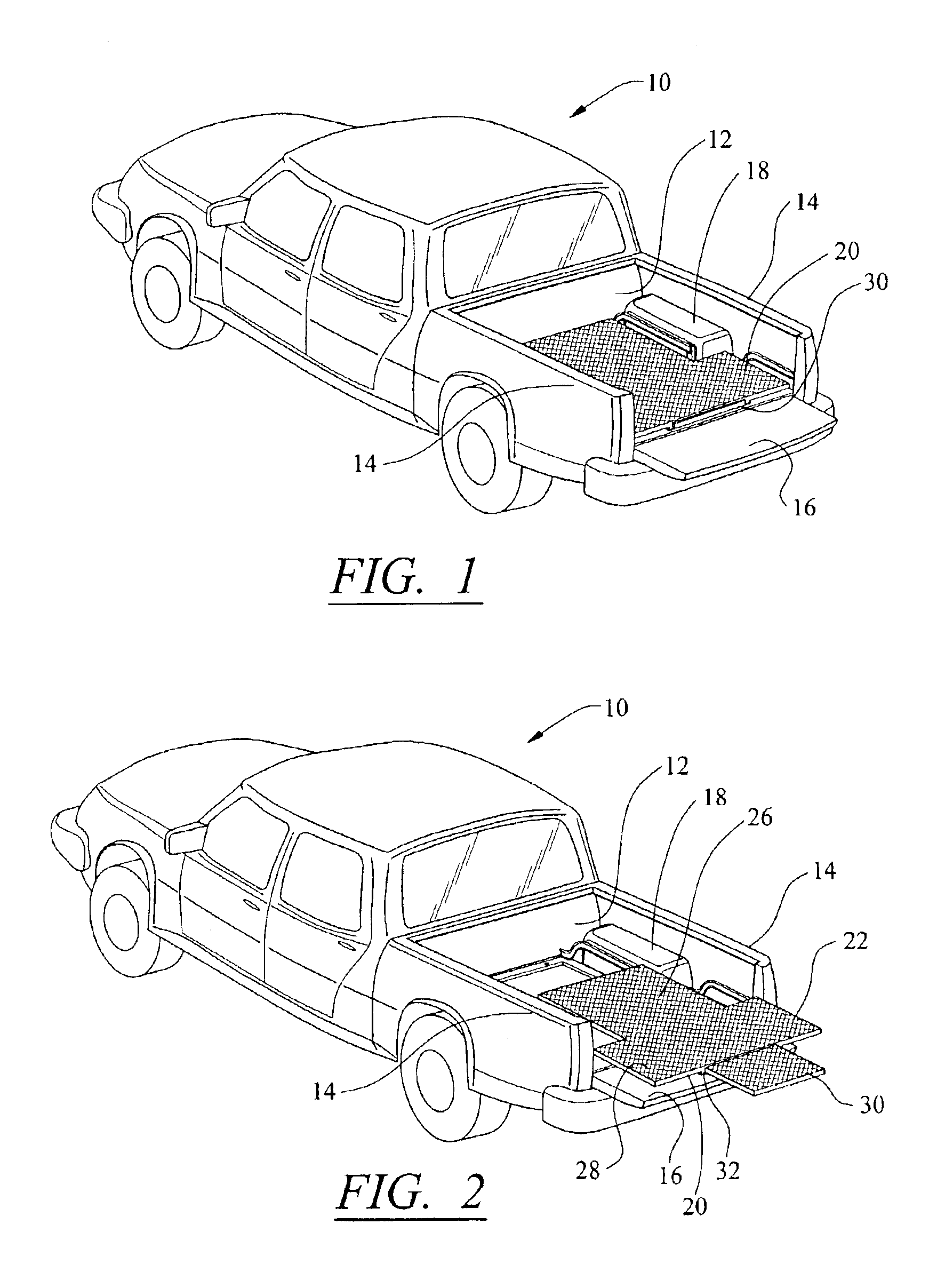
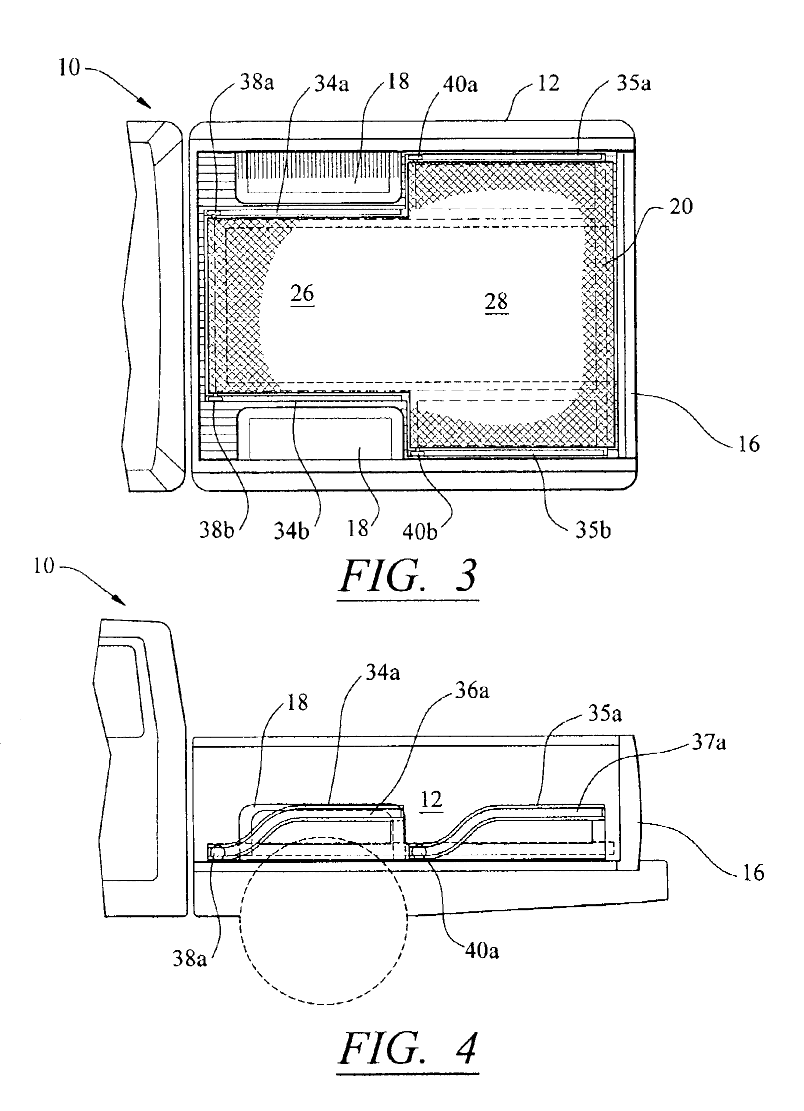
[0026]The invention is best understood by referring to FIGS. 1-6 which illustrate a well known commercially available truck generally indicated by reference numeral 10 having a bed 12 having the side panels 14, tail gate 16 and the pair of wheel wells 18. In accordance with this invention the load carrying platform 20 is slidably mounted in the bed 12 and as will be described hereinbelow is slidable toward the aft end of the bed 12 and a cam arrangement raises the platform 20 to the level of the wheel wells 18 when it is fully deployed. The platform 20...


PUM


Abstract

The load carrying capability of a bed of a truck or the back of an SUV is increased by length and weight of the load by including a platform that is movable to the height of the wheel well so that a load that measures say, 4′×8′ fits above the wheel well so that the limited space between wheel wells do not impair the load and the wheel wells absorb part of the load. In one embodiment a camming arrangement with a guide rail cam and roller followers attached to the platform place the platform in sliding relationship and raises the platform as it slides rearwardly. In another embodiment a foldable linkage is utilized to raise the platform. Jack can be employed to raise the platform and a brake is added prevent the platform from moving backwards once deployed.

Description

TECHNICAL FIELD[0001]This invention relates to apparatus for extending the carrying capacity of a truck or sports utility vehicle or the like, and particularly to provide a platform that serves to permit a wider, longer load and / or enhance the load carrying capability of the platform.BACKGROUND OF THE INVENTION[0002]As is well known in the automotive technology, the size of the beds of trucks vary considerably and there is a recent trend, although subject to change, where the beds are made shorter than was heretofore the case such that the length is as short as 4-6.5 feet (′). Obviously, this has an adverse affect on the truck's ability to haul large loads, as for example, sheets of sheet rock, ply wood, etc that measures say, 4′×8′.[0003]There are a number of devices that are on the market and described in the literature that address this problem. One such device, for example, is a tiered bracket that is pivotally mounted at the end of the truck bed that allows one to slide the lar...

Claims


Application Information

Patent Timeline
Patent Type & Authority Patents(United States)
IPC IPC(8): B60P1/00B60P3/40
CPCB60P3/40
Inventor ERVIN, DAVID R.
Owner ERVIN DAVID R
Learn More