Vehicle lamp and method

a technology for vehicles and lamps, applied in the field of vehicles, can solve problems such as the limitation of the inside layout of headlamps, and achieve the effect of good visibility

Inactive Publication Date: 2005-07-26
STANLEY ELECTRIC CO LTD
View PDF8 Cites 16 Cited by
  • Summary
  • Abstract
  • Description
  • Claims
  • Application Information

AI Technical Summary

Benefits of technology

[0019]The present invention has been devised in view of the above and other problems. The present invention can provide a vehicle lamp which is capable of emitting light to a lateral direction and which has a simple construction so as to reduce design limitations as much as possible. The present invention can also provide a vehicle lamp capable of achieving desired light distribution characteristics by controlling the directions and intensities of light illuminated in ranges covering the front and the side of the vehicle.
[0026]According to the above construction, direct light from the light source or reflected light from the first reflecting surface enters the projection lens and is beamed toward front. At this time, the shutter blocks part of light to be incident into the projection lens, so that the light distribution characteristics are those of a low beam which does not cause glare to an oncoming vehicle.
[0027]Part of the light emitted from the light source is reflected by the second, third, and fourth reflecting surfaces in turn, and illuminates at least one predetermined range covering the side and / or front of the vehicle. These reflecting surfaces thus provide additional light for supplementing the light from the projection lens for illuminating the front and the side of the vehicle. Thereby, the lamp offers better visibility as it illuminates the driving direction of the vehicle, particularly when driving on a winding road or making a left or right turn, or a U-turn.
[0028]Since part of the light emitted from the light source is used for illuminating the side of the vehicle by the fourth reflecting surface, i.e., forward and upward light beams from the light source are directed by the second, third, and fourth reflecting surfaces to the lateral direction, the amount of light for illuminating the front through the projection lens is not decreased. That is, the forward and upward light beams from the light source, which were conventionally not utilized, are efficiently used.
[0030]This means that the optical path is made to change its direction by the fourth reflecting surface located at a relatively far front portion of the lamp to the lateral direction, and therefore, in this particular embodiment of the invention, the front lens need not extend as far as to the side face for covering the light emitting region of the third reflecting surface as in the related art. This allows more freedom in layout of the accessory inside the lamp, which in turn leads to more freedom in design of the entire lamp.
[0035]For example, the fourth reflecting surface may be rotated in accordance with the steering angle, or by some other switch activating means. By thus adjusting the illuminating direction of the reflected light from the fourth reflecting surface enabling real-time control of the illumination intensity over a particular range covering the front and side of the vehicle, desired light distribution characteristics can be achieved as required in various situations, e.g., the frontward lighting during driving on a straight road may be switched to sideward lighting when driving on a winding road or making a left or right turn, so that the lamp always offers good visibility in the driving direction.

Problems solved by technology

Also, because of the need to secure this lateral optical path, there are limitations on the inside layout of the headlamp 90 or installation space of the accessory 99, which is usually fitted in this side portion of the headlamp 90.

Method used


Image

  • Vehicle lamp and method
  • Vehicle lamp and method
  • Vehicle lamp and method

Examples


Embodiment Construction

[0049]Preferred embodiments of the present invention will be hereinafter described in detail with reference to FIG. 4A to FIG. 11.

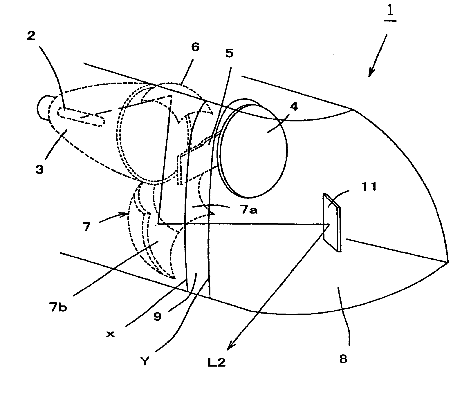
[0050]FIGS. 4A-4C and FIG. 5 illustrate a vehicle lamp according to one embodiment of the present invention.

[0051]The vehicle lamp 1 in these drawings is illustrated as a headlamp to be mounted on the right side portion of a vehicle body. The vehicle lamp 1 can include a bulb 2 as a light source, a first reflecting surface 3, a projection lens 4, a shutter 5, a second reflecting surface 6, a third reflecting surface 7, a fourth reflecting surface 11, and a front lens 8. The first reflecting surface 3 is arranged to surround the bulb 2, so as to reflect light from the bulb 2 toward front. The projection lens 4 is arranged forward of the bulb 2, and it converges direct light from the bulb 2 or reflected light from the first reflecting surface 2 to a predetermined extent. The shutter 5 is arranged in the main optical path of direct light from the bulb 2 or r...


PUM


Abstract

A vehicle lamp emitting light to a lateral direction can include a simple construction to reduce design limitations, and can achieve desired light distribution characteristics by controlling the direction and intensity of light illuminated in a range covering the front and the side of the vehicle. The vehicle lamp preferably includes: a second reflecting surface for reflecting incident light from a light source to a predetermined direction; a third reflecting surface, arranged forward of the light source and backward of a projection lens and out of a main optical path, for reflecting light from the second reflecting surface toward front; and a fourth reflecting surface, arranged forward of the third reflecting surface and out of the main optical path, for reflecting light from the third reflecting surface to a lateral direction relative at least to a region of light emitted from the projection lens along the main optical path.

Description

[0001]This invention claims the benefit of Japanese Patent Application No. 2002-137130 filed on May 13, 2002, the disclosure of which is hereby incorporated by reference.BACKGROUND OF THE INVENTION[0002]1. Field of the Invention[0003]The present invention relates to vehicle lamps used as headlamps or auxiliary front lamps such as fog lamps. More particularly, it relates to vehicle lamps that are capable of emitting light that includes a component of the light directed in a lateral direction.[0004]2. Description of the Related Art[0005]One example of a related or conventional vehicle lamp capable of emitting light into a lateral direction is shown in FIG. 1A to FIG. 1C. In this specification, a front to back direction or a left to right direction refers to a corresponding direction viewed from a reference point, which is a headlamp mounted on a vehicle body. For example, “front”, “frontward”, or “forward” means the main illuminating direction or the direction of optical axis of a lig...

Claims


Application Information

Patent Timeline
Patent Type & Authority Patents(United States)
IPC IPC(8): B60Q1/12B60Q1/04F21V7/00F21S8/12F21S8/10F21V14/04F21V14/00F21V11/16F21V11/00F21V7/16F21V13/00F21W101/10F21Y101/00
CPCB60Q1/12F21S48/1388F21S48/1757F21S48/145F21S41/162F21S41/17F21S41/321F21S41/43F21S41/675F21S41/365F21W2102/19
Inventor TANIUCHI, HITOSHI
Owner STANLEY ELECTRIC CO LTD
Why Eureka
Try Eureka