Patient temperature repeating system and method

a patient temperature and repeating technology, applied in the field of patient temperature monitoring, can solve the problems of one or more instruments obtaining inaccurate patient temperature readings from the sensor, limited number of sites, etc., and achieve the effect of reducing the potential of the patient temperature sensor and enhancing the ability of clinicians

Inactive Publication Date: 2005-07-26
MEDIVANCE
View PDF45 Cites 49 Cited by
  • Summary
  • Abstract
  • Description
  • Claims
  • Application Information

AI Technical Summary

Benefits of technology

[0004]Accordingly, the present invention provides a patient temperature repeating system and a method of repeating patient temperature information from a resistive-type patient temperature sensor (e.g., a thermistor, a resistive temperature device, or the like) that allow one or more medical instruments to utilize a single patient temperature sensor. The system and method of the present invention provide for the accessibility of the resistance level of the patient temperature sensor, and hence patient temperature information, by one or more medical instruments without requiring direct connection of the patient temperature sensor with the medical instrument(s). The system and method of the present invention enhance the ability of clinicians to obtain patient temperature information from a single appropriate site in a timely and efficient manner while reducing the potential that the patient temperature sensor might provide inaccurate temperature information to one or more of the medical instruments.

Problems solved by technology

However, there are a limited number of sites that provide suitable access for such resistive-type patient temperature sensors.
Thus, connecting multiple instruments to a single temperature sensor can result in one or more of the instruments obtaining inaccurate patient temperature readings from the sensor.

Method used


Image

  • Patient temperature repeating system and method
  • Patient temperature repeating system and method
  • Patient temperature repeating system and method

Examples


Embodiment Construction

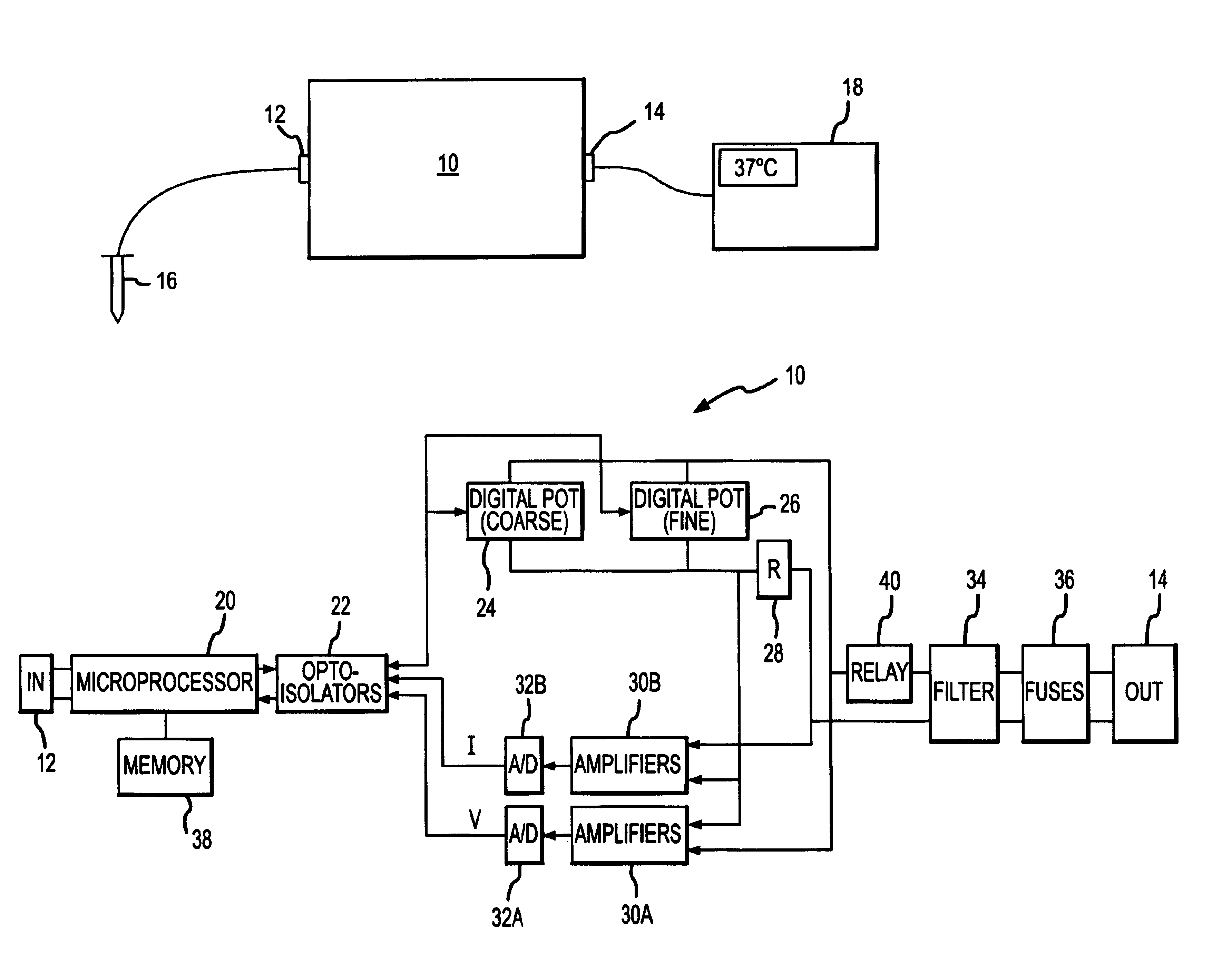
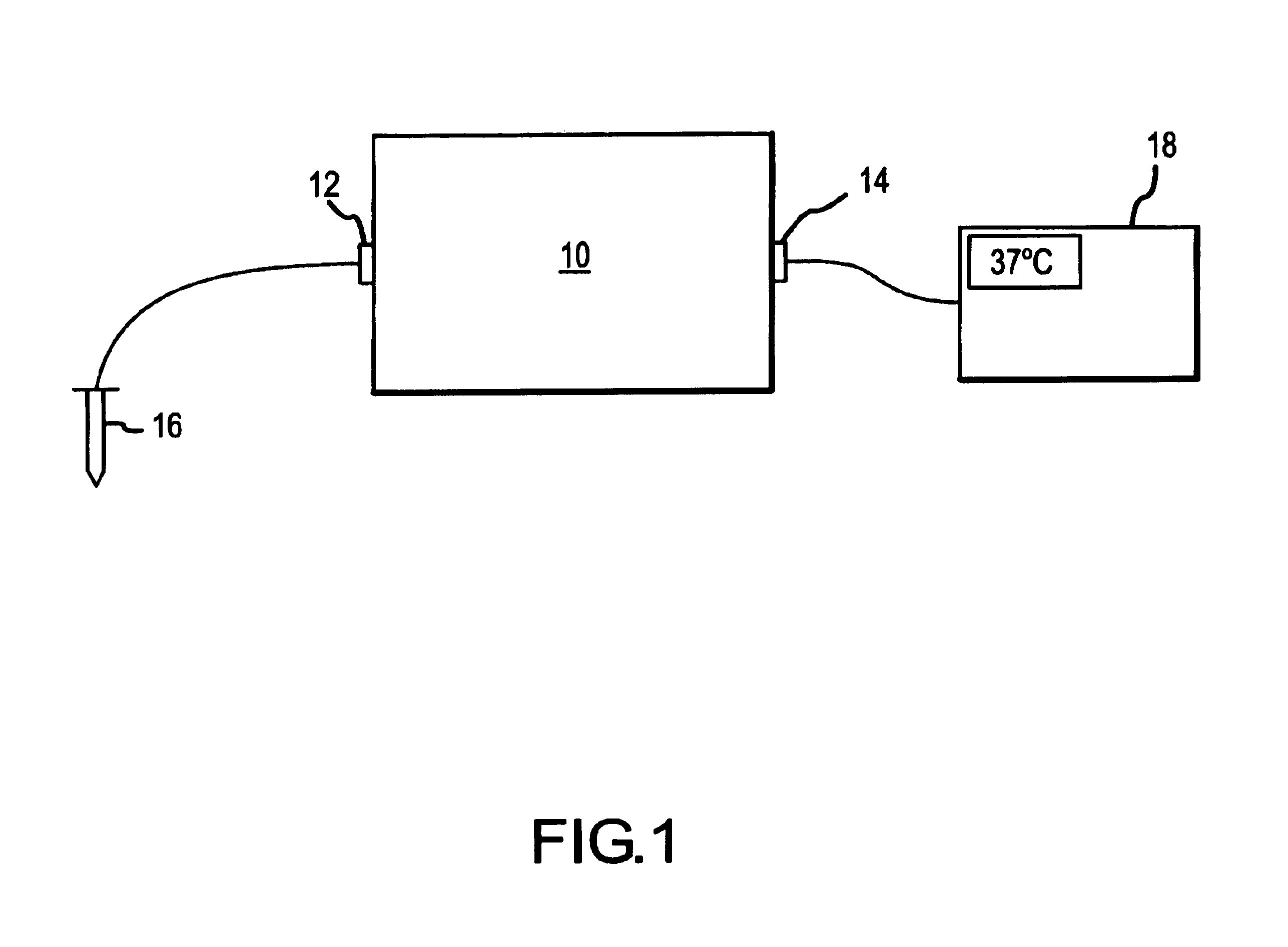
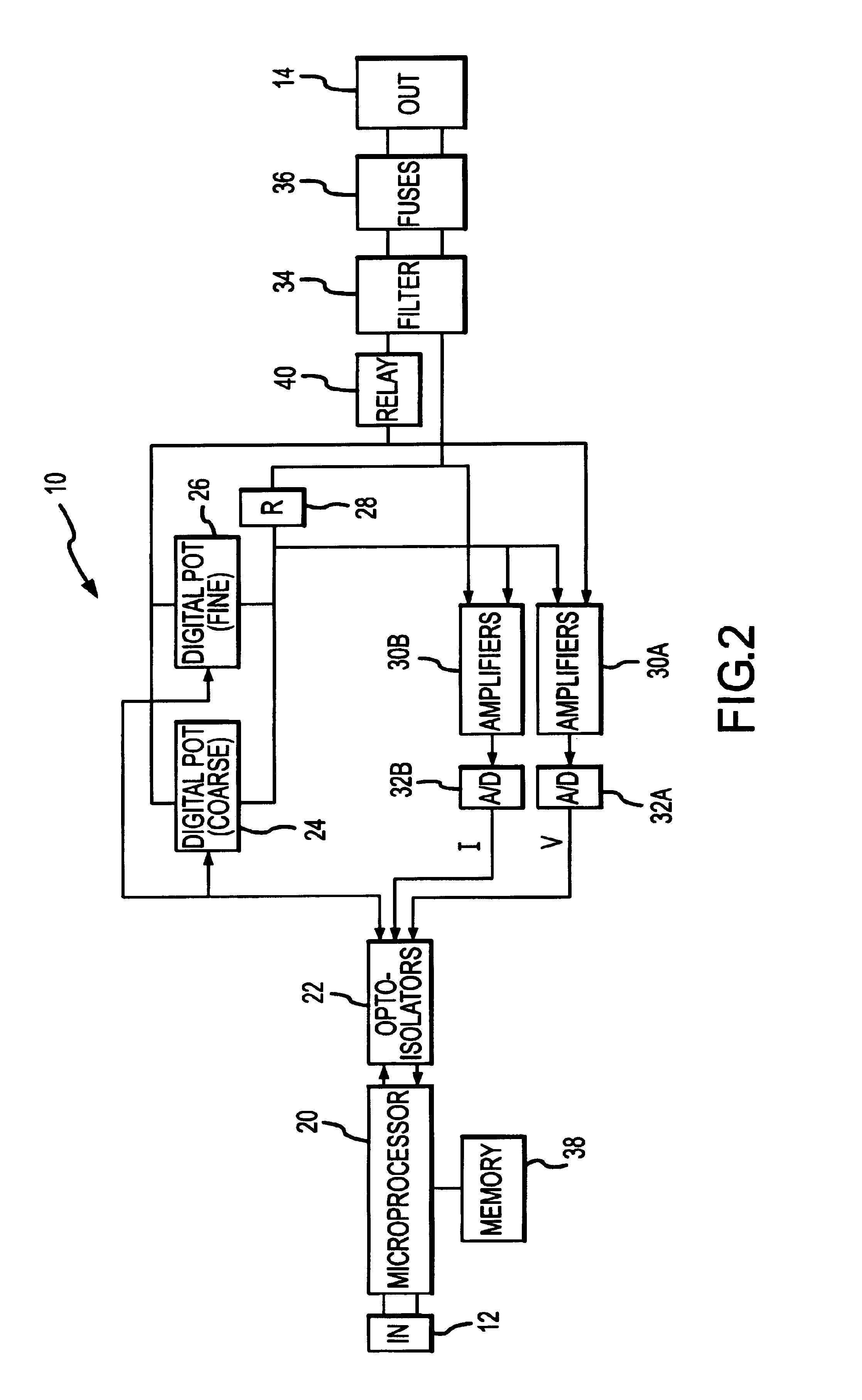
[0020]Referring to FIG. 1, there is shown a block diagram of one embodiment of a patient temperature repeating system 10. The patient temperature repeating system 10 includes an input connector 12 and an output connector 14. The input connector 12 is configured for connection of a resistive-type temperature sensor 16 to the patient temperature repeating system 10. In this regard, the input connector 12 may be a plug-type connector configured for receiving the plug of, for example, a YSI-400 series thermistor probe available from YSI Incorporated. The output connector 14 is configured for connection of a medical instrument 18 to the patient temperature repeating system 10. In this regard, the output connector 14 may be a plug-type connector for receiving the plug of a cable connected to the medical instrument 18. The output connector 14 permits multiple medical instruments to be easily switched in and out by simply removing the plug connector of one instrument 18 and inserting the pl...


PUM

PropertyMeasurementUnit
resistanceaaaaaaaaaa

Abstract

A patient temperature repeating system and a method of repeating patient temperature information from a resistive-type patient temperature sensor allow one or more medical instruments to utilize a single patient temperature sensor. In one embodiment, the patient temperature repeating system (10) includes input and output connectors (12, 14), a microprocessor (20), optical isolators (22), a coarse digital potentiometer (24) in parallel with a fine digital potentiometer (26), a current sense resistor (28), amplifiers (30A, 30B), analog-to-digital converters (32A, 32B), a filter (34), fuses (36), a non-volatile memory device (38), and a relay (40). In operation, the microprocessor (20) reads the resistance level of a resistive-type patient temperature sensor (16) connected to the input connector (12) and provides the appropriate control signals through the optical isolators (22) to the coarse and fine digital potentiometers (24, 26) in order to set the resistance seen by a medical device (18) connected to the output connector (14) to match that of the patient temperature sensor (16).

Description

FIELD OF THE INVENTION[0001]The present invention relates generally to patient temperature monitoring, and more particularly to providing medical instruments with patient temperature related information from a single patient temperature sensor.BACKGROUND OF THE INVENTION[0002]Clinicians and other persons involved in providing medical care to patients often wish to use a number of medical instruments and the like that require the use of a patient temperature sensor in order to obtain the temperature of the patient. Often, the patient temperature sensor is a resistive-type sensor (i.e. a sensor that varies its resistance level in accordance with the temperature of a patient on which the sensor is placed such as a thermistor temperature probe). To obtain patient temperature information, a medical instrument supplies an excitation voltage or current to the resistive-type temperature sensor in order to read the resistance level of the sensor. The resistance level of the sensor can then b...

Claims


Application Information

Patent Timeline
Patent Type & Authority Patents(United States)
IPC IPC(8): G01K1/02G01K13/00G01K1/00A61B5/01
CPCG01K1/026G01K13/002G01K13/20
Inventor GRUSZECKI, GARY A.CARSON, GARY A.PROCTOR, ROBERT W.
Owner MEDIVANCE
Why Eureka
Try Eureka