Flange bearing

a technology of flange bearings and bearings, which is applied in the direction of bearings, shafts and bearings, rotary bearings, etc., can solve the problems of increasing the amount of manufacturing time, increasing the number of manufacturing processes, and increasing the cost of constructing each of the flanges of the journal bearing with oil grooves and contoured surfaces. , to achieve the effect of fewer manufacturing steps

Inactive Publication Date: 2005-07-26
FEDERAL MOGUL WORLD WIDE LLC
View PDF13 Cites 24 Cited by
  • Summary
  • Abstract
  • Description
  • Claims
  • Application Information

AI Technical Summary

Benefits of technology

[0010]One advantage of the invention is that an inexpensive thrust bearing is provided having a bi-directional loading capabilities with only one contoured thrust face on each bearing half arranged longitudinally opposite one another.
[0011]Another advantage of the invention is providing a split engine bearing requiring fewer manufacturing steps, namely eliminating the formation of a contoured surface on a thrust face of each bearing.
[0012]Another advantage of the invention is that the bearing halves may be identical in construction but oriented with their contoured thrust surfaces opposite one another to achieve bi-directional loading.

Problems solved by technology

In manufacture, constructing each of the flanges of the journal bearing with oil grooves and contoured surfaces comes at a cost.
The number of manufacturing processes is increased, the amount of manufacturing time is increased, the amount of required tooling is increased, potential scrap is increased, and the amount of labor is increased, among other associated costs throughout the manufacturing process.

Method used


Image

  • Flange bearing
  • Flange bearing
  • Flange bearing

Examples


Embodiment Construction

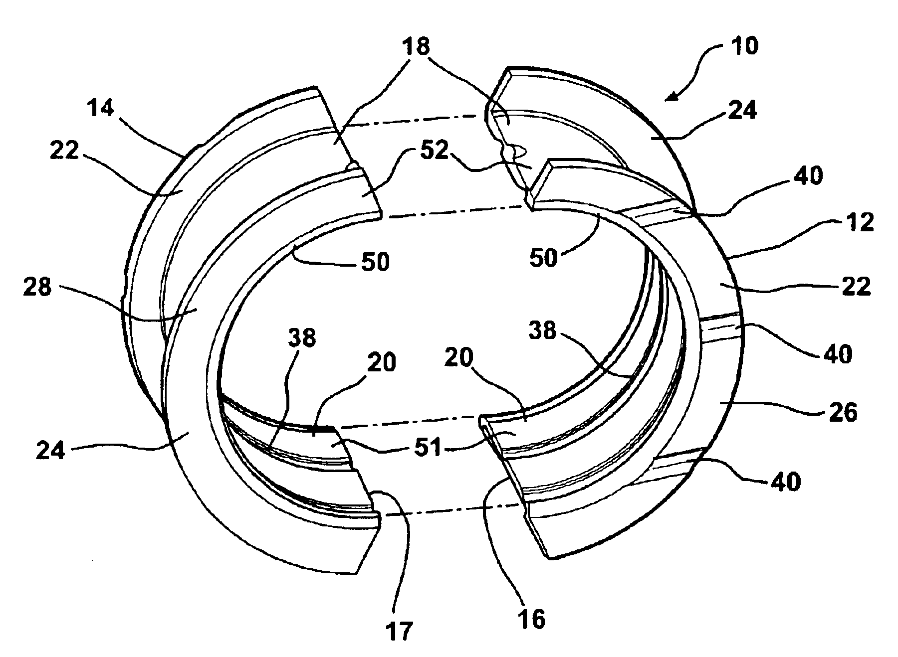
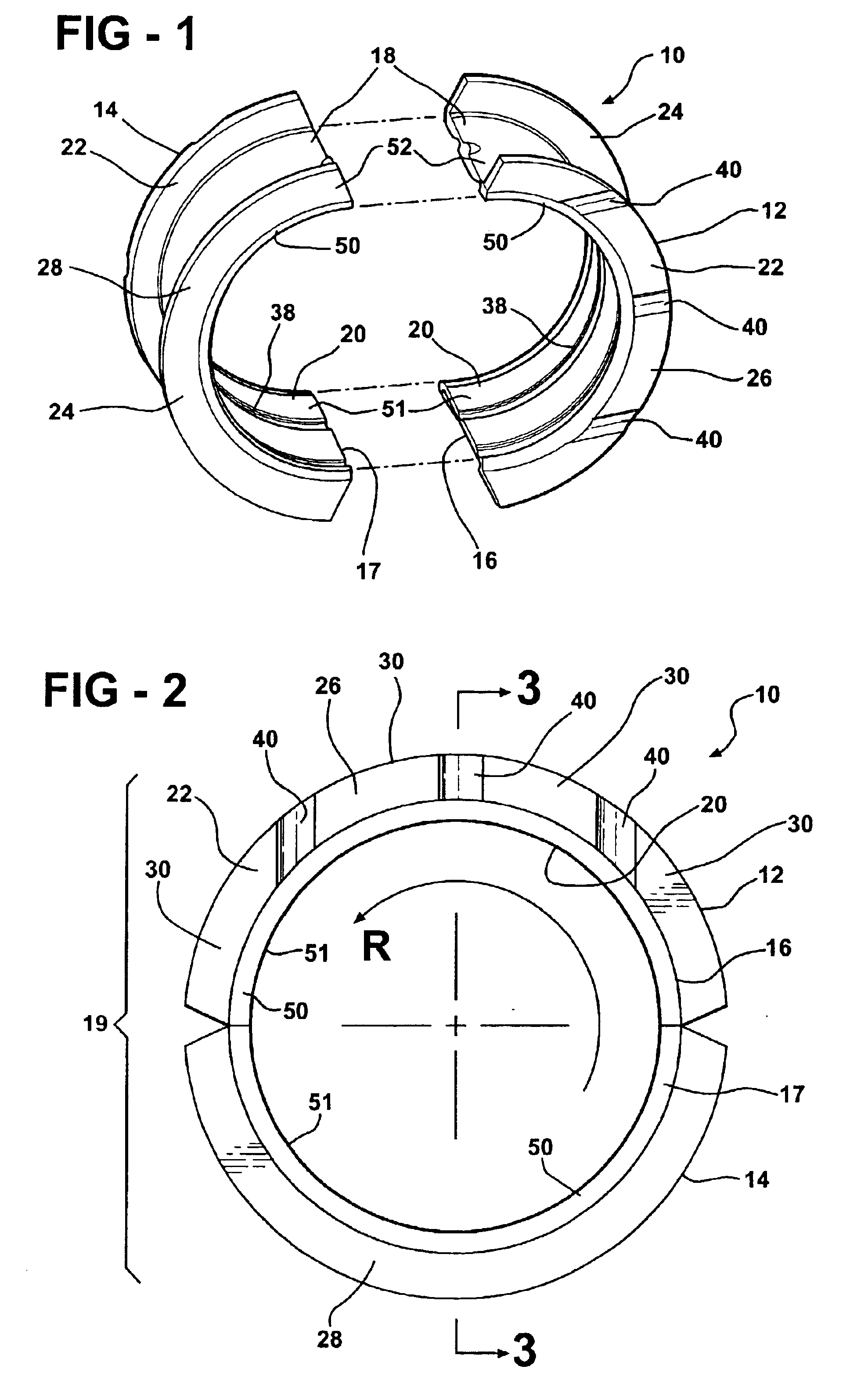
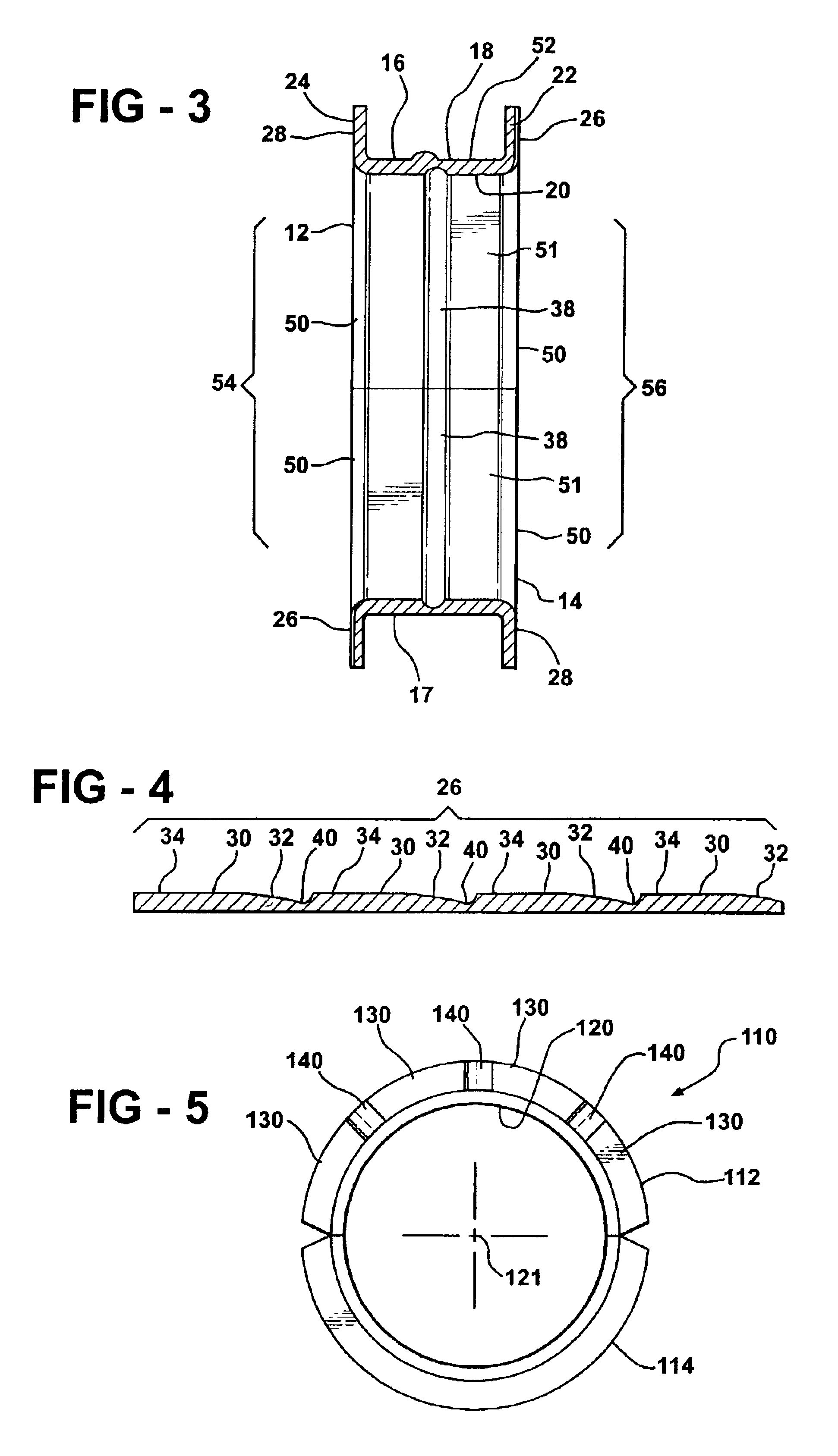
[0019]A presently preferred embodiment of an engine thrust bearing constructed according to the present invention is shown generally at 10 in FIGS. 1-3. The engine bearing 10 is comprised of a pair of separately constructed engine bearing halves 12, 14, wherein each half 12, 14 is preferably identical to the other in construction. The engine bearing halves 12, 14 have generally arcuate shells 16, 17 disposed in abutting end-to-end engagement about a longitudinal axis 21 of the bearing 10, such that when the halves 12, 14 are assembled, the shells 16, 17 form a generally cylindrical shell 19 defining an outer surface 18 and a bore or inner surface 20 of the engine bearing. Each half 12, 14 has a pair of longitudinally spaced thrust flanges 22, 24 extending radially outwardly from each shell 16, 17.

[0020]The flange 22 of bearing half 12 has a contoured thrust face 26, while the opposite flange 24 of bearing half 12 has a generally non-contoured thrust face 28. The other bearing half 1...


PUM


Abstract

An engine bearing for an internal combustion engine has a pair of separately constructed bearing halves comprising a pair of arcuate shells having a pair of laterally spaced flanges extending generally radially outwardly from each shell. Each pair of laterally spaced flanges comprises a pair of thrust faces facing generally away from one another with one of the thrust faces comprising an undulating contoured surface and the other thrust face having a generally planar non-contoured surface. The engine bearing is assembled having the contoured surface of one engine bearing half abutting the non-contoured surface of the other engine bearing half so that the engine bearing has generally opposite sides comprising both contoured and non-contoured surfaces.

Description

BACKGROUND OF THE INVENTION[0001]1. Field of the Invention[0002]The invention relates generally to engine bearings for internal combustion engines, and more particularly to engine bearings having radially outwardly extending flanges for accommodating thrust loads.[0003]2. Related Art[0004]It is common to support internal combustion engine crankshafts with journal bearings located at axially spaced locations along the crankshaft. Each journal bearing typically includes a pair of mating halves including an upper half bearing seated in an arcuate recess in a lower part of an engine block, and a lower half bearing seated in an arcuate recess of a cap. The cap is typically bolted to the engine block to retain the two bearing halves encircled about the crankshaft.[0005]Of the journal bearings spaced along the crankshaft, typically, at least one journal bearing is designed to take an axial thrust load applied by the crankshaft. A crankshaft journal bearing capable of withstanding thrust lo...

Claims


Application Information

Patent Timeline
Patent Type & Authority Patents(United States)
IPC IPC(8): F16C33/04F16C33/10F16C9/00F16C9/02F16C17/00F16C17/04F16C17/10
CPCF16C9/02F16C17/10F16C33/1075F16C17/047
Inventor WELCH, SEAN MICHAELTHOMPSON, RONALD J.
Owner FEDERAL MOGUL WORLD WIDE LLC
Why Eureka
Try Eureka