Plasma display panel

a technology of display panels and plasma, which is applied in the direction of gas discharge vessels/containers, electrodes, gas-filled discharge tubes, etc., can solve the problems of increasing power consumption, achieve excellent display characteristics, reduce manufacturing steps, and consume less power

Inactive Publication Date: 2006-07-06
PANASONIC CORP
View PDF6 Cites 3 Cited by
  • Summary
  • Abstract
  • Description
  • Claims
  • Application Information

AI Technical Summary

Benefits of technology

[0026] The foregoing structure allows achieving a PDP excellent in display characteristics and consuming a fewer power and also being manufactured with a fewer manufacturing steps.

Problems solved by technology

However, when the black layer and the light blocking layer are commonly used as discussed above, electrostatic capacitance increases in the light blocking layer as a resistance of the black layer decreases, so that the power consumption increases.

Method used


Image

  • Plasma display panel
  • Plasma display panel
  • Plasma display panel

Examples


Embodiment Construction

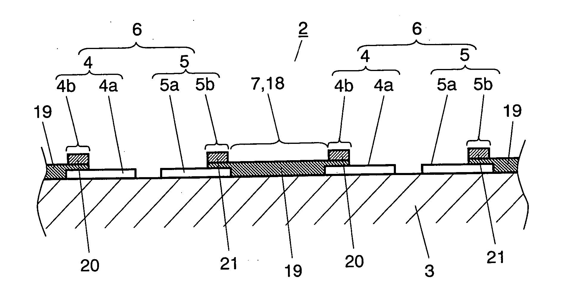
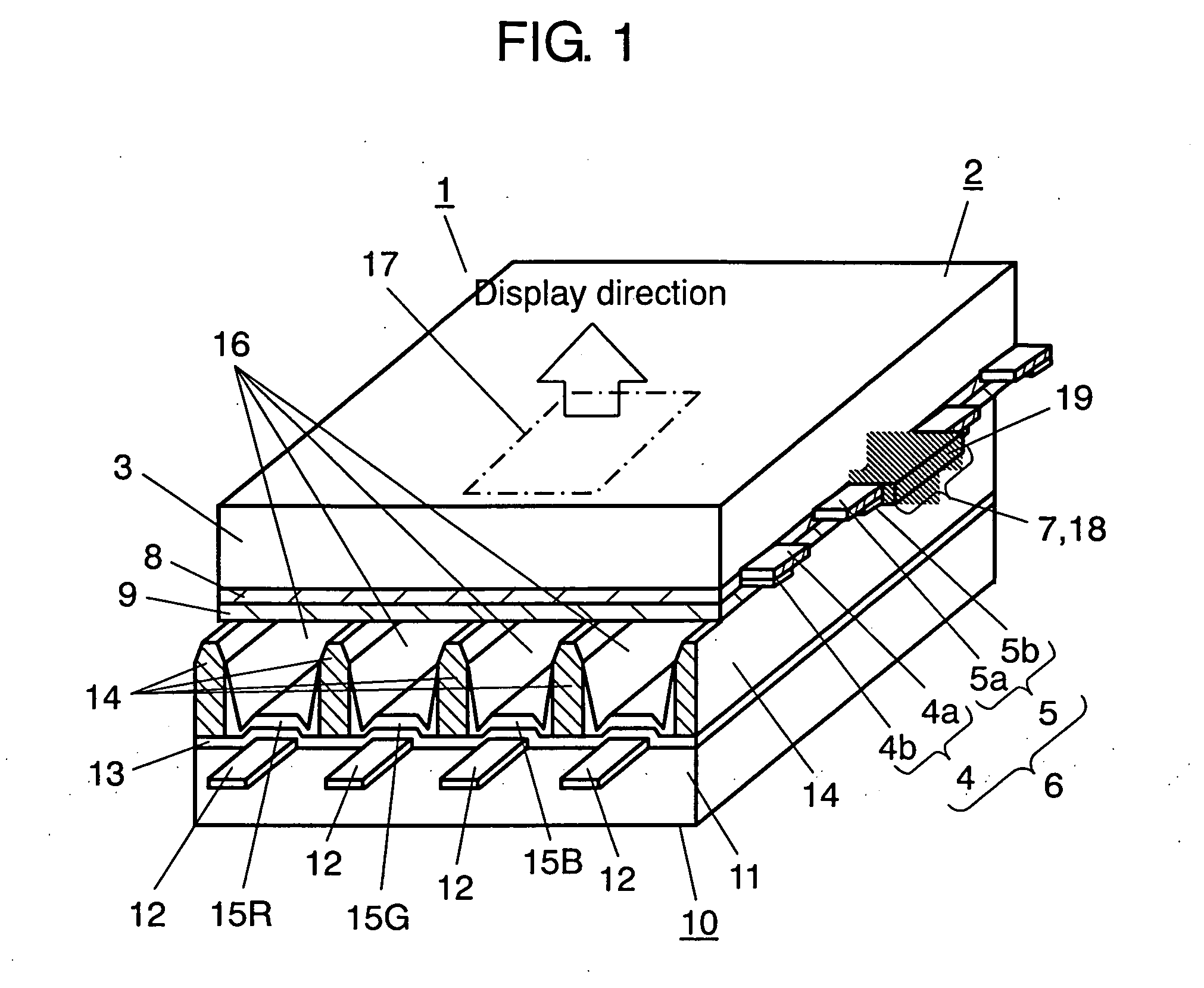
[0030] A PDP in accordance with an exemplary embodiment of the present invention is demonstrated hereinafter with reference to the accompanying drawings. FIG. 1 shows a perspective sectional view illustrating a schematic structure of the PDP in accordance with an exemplary embodiment of the present invention.

[0031] Front plate 2 of PDP 1 comprises the following elements:

[0032] substrate 3 facing the front and formed by a float method, like a sheet of glass, and being smooth, transparent and insulating;

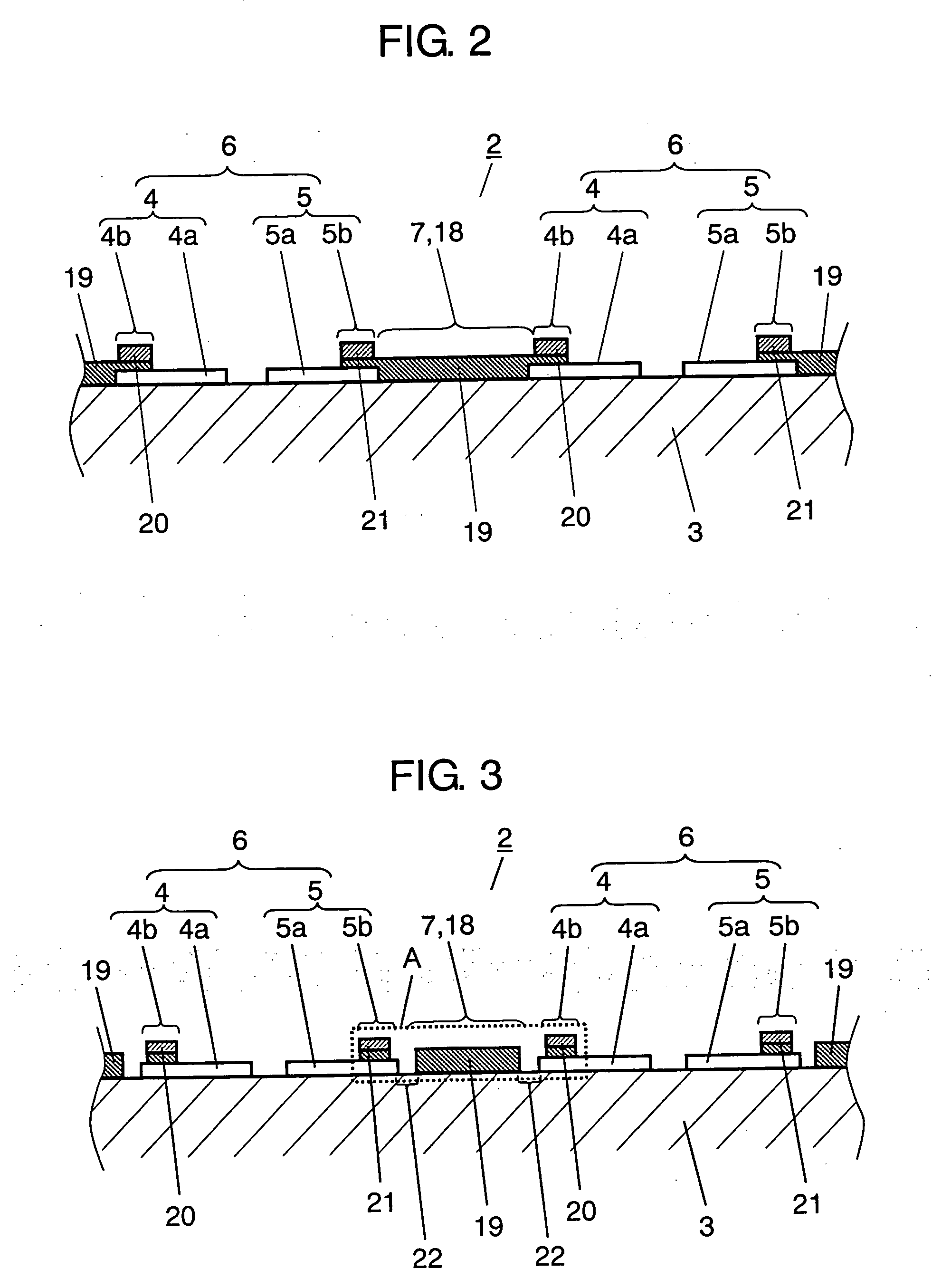
[0033] display electrode 6 formed of scan electrode 4 and sustain electrode 5 prepared on a principal plane of substrate 3;

[0034] light blocking section 7 formed on the principal plane and prepared between display electrodes 6 adjacent to each other;

[0035] dielectric layer 8 covering both of the display electrodes and light blocking sections 7; and

[0036] protective layer 9 made of e.g. MgO and covering dielectric layer 8.

[0037] Each on of scan electrodes 4 and sustain electrodes...


PUM


Abstract

A plasma display panel is disclosed. It can display quality videos and its manufacturing steps can be reduced. A pair of substrates (3), (11) confront each other to form dischargeable space (16) in between. At least front one (3) of the substrates is transparent, and includes display electrodes (6) formed of scan electrodes (4) and sustain electrodes (5), as well as light-blocking sections (7) corresponding to non-dischargeable sections (18) disposed between the display electrodes (6). The other substrate (11) facing to rear includes phosphor layers (15R), (15G), (15B) which emit light by discharging. Each one of display electrodes (6) is formed of transparent electrodes (4a), (5a) and bus electrodes (4b), (5b) which are formed of a plurality of electrode-layers. At least one of the electrode-layers is made of black layer (19) having a specific volume resistance ranging from 1×10⁵ Ωcm to 1×10⁹ Ωcm, and light-blocking sections (7) are made of identical material of black layer (19).

Description

TECHNICAL FIELD [0001] The present invention relates to plasma display panels to be used in plasma display devices that are known as display devices featuring a large size screen, and yet, a thin body and a light weight BACKGROUND ART [0002] A plasma display panel (hereinafter referred to as PDP) displays videos by the following method: generating ultraviolet rays by gas discharge, then the ultraviolet rays excite phosphor to emit light. [0003] The PDPs are divided into two types in terms of driving methods, namely, an AC driven PDP and a DC driven PDP, and two discharge methods are available in PDPs, namely, a surface discharge PDP and an opposed discharge PDP. Presently the AC driven and surface discharge PDP having three electrodes becomes a mainstream in the market, which requires PDPs of a higher resolution, easiness for increasing a screen size, a simpler structure, and easiness for manufacturing. [0004] The AC driven PDP is formed of a front plate and a rear plate. The front ...

Claims


Application Information

Patent Timeline
Patent Type & Authority Applications(United States)
IPC IPC(8): H01J61/04H01J11/12H01J11/22H01J11/24H01J11/26H01J11/34
CPCH01J11/44H01J2211/225H01J2211/444
Inventor ADACHI, DAISUKEYONEHARA, HIROYUKIKUBOTA, TOSHIMOTO
Owner PANASONIC CORP
Why Eureka
Try Eureka