Amphibious vehicle

a technology for amphibious vehicles and boats, applied in the direction of boats, marine propulsion, retractable wheels, etc., can solve the problems of compromising the maneuverability of the vehicle in the water, presenting certain limitations to the use of the vehicle, and the inability of amphibious vehicles to operate at a high speed in the water. achieve the marine performance and maneuverability of a conventional boa

Inactive Publication Date: 2005-07-26
HEWITT STANLEY C
View PDF23 Cites 52 Cited by
  • Summary
  • Abstract
  • Description
  • Claims
  • Application Information

AI Technical Summary

Benefits of technology

[0019]With the caterpillar track assemblies in the raised position, stowed on or above the hull's deck, the caterpillar track assemblies are fully removed from the water. Because drag from the caterpillar track assemblies is eliminated during marine operation, the amphibious vehicle achieves the marine performance and maneuverability of a conventional boat. Because the track assemblies rotate generally about, or offset from, an inboard edge, the track assemblies can be rotated into an upright position wherein the amphibious vehicle has a narrower overall width than with the tracks extended into their downward position.
[0023]Accordingly, it is a principal object of the invention to provide an amphibious vehicle with improved performance and maneuverability.
[0026]It is an object of the invention to provide improved elements and arrangements thereof for the purposes described which is inexpensive, dependable and fully effective in accomplishing its intended purposes.

Problems solved by technology

The inability to remove the driving assembly from the water means that the amphibious vehicle cannot be operated at a high speed in the water because of the high drag caused by the submerged driving assembly.
Maneuverability in the water is also compromised by the additional drag.
The width of the amphibious vehicle, with tracks mounted along side, presents certain limitations to use of the vehicle.
One such limitation is found if the vehicle is to be trailered.
While this approach leaves the hull cleaned up for improved marine performance, it is a relatively complex solution.

Method used


Image

  • Amphibious vehicle
  • Amphibious vehicle
  • Amphibious vehicle

Examples


Embodiment Construction

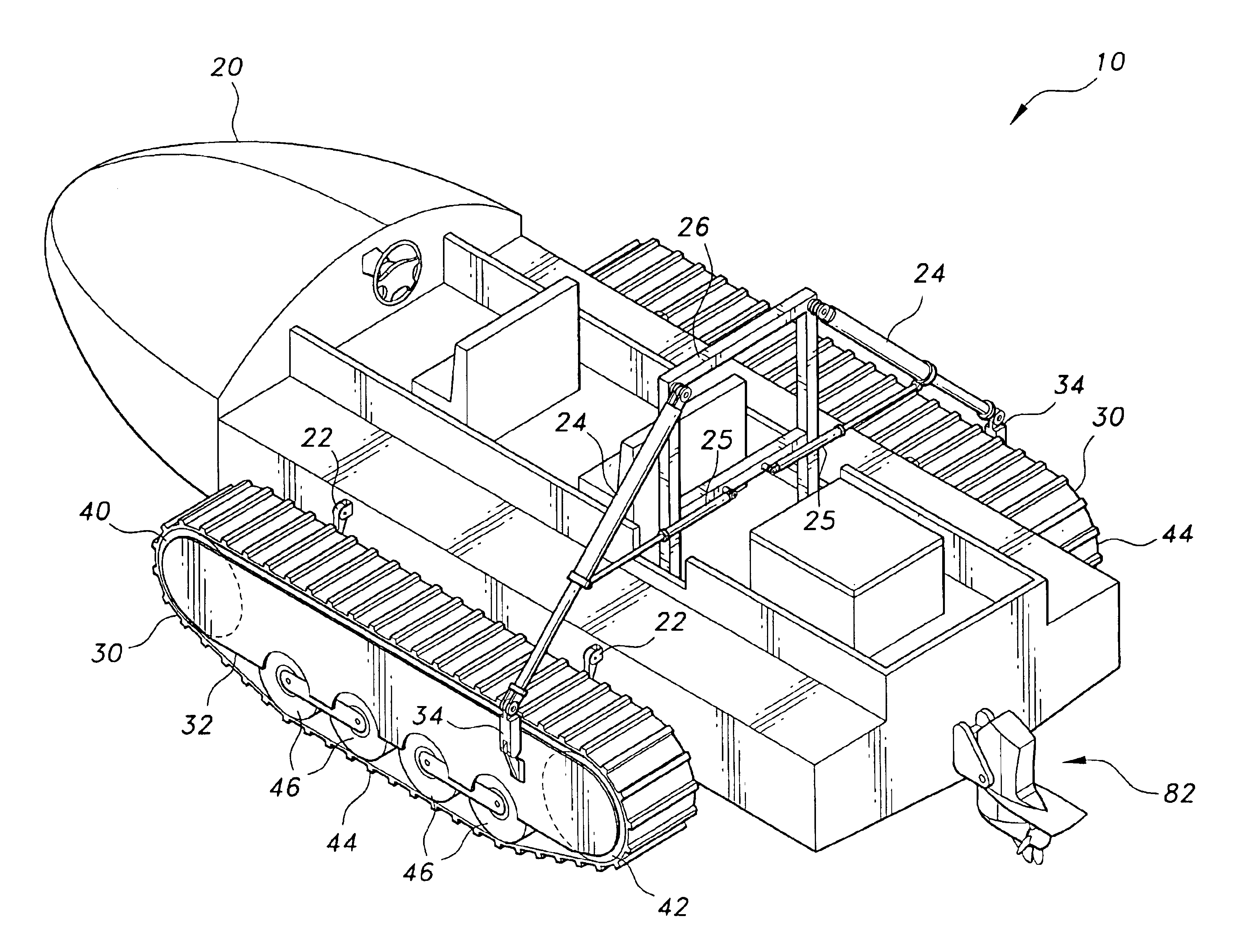
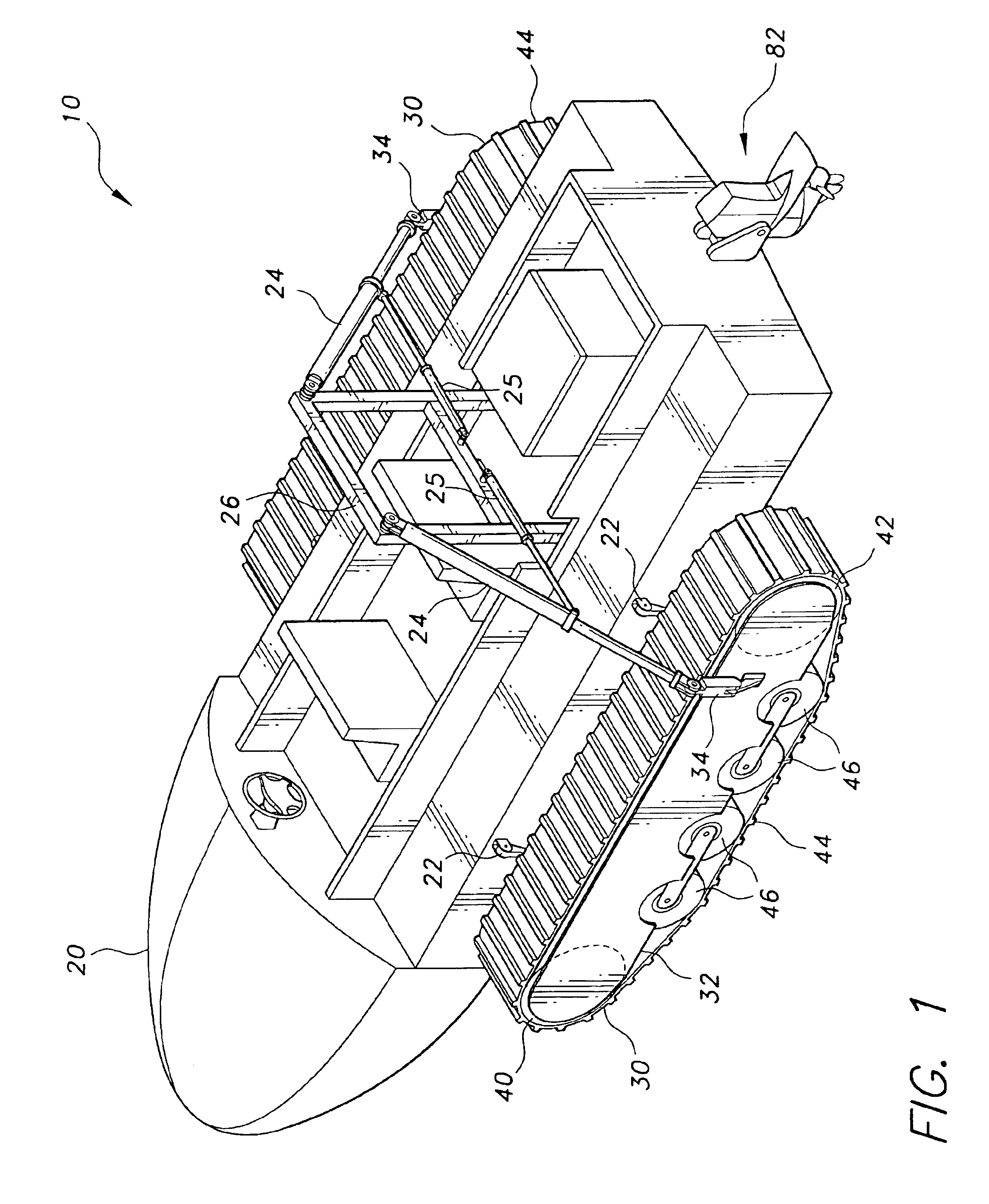
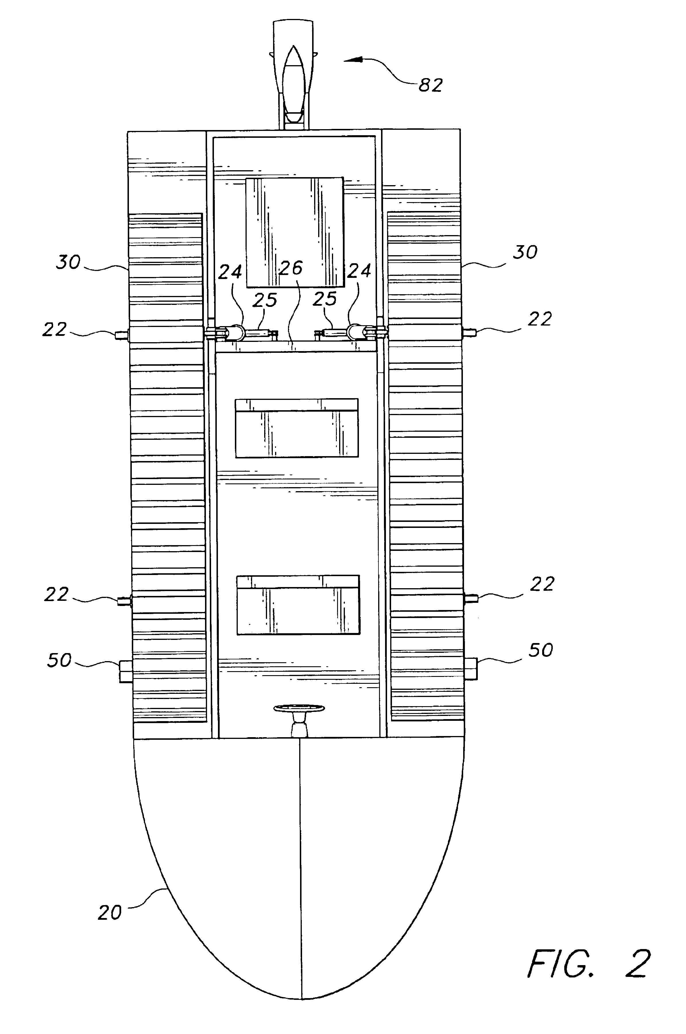
[0040]The present invention is an amphibious vehicle, designated generally as 10 in the drawings. Referring to FIGS. 1-3, the amphibious vehicle 10 includes a hull 20, and track assemblies 30. The track assemblies 30 are mounted longitudinally alongside the hull 20 by hinges 22. The hinges 22 allow the track assemblies 30 to be rotated between a lowered position, where they support the amphibious vehicle 10 and provide traction and propulsion during land operation, and a raised position, where they rest on the deck of the hull 20 during marine operation, clear of the waterline of the hull 20. With the track assemblies 30 clear of the waterline during marine operation, they present no drag to hinder marine performance. The track assemblies 30 provide propulsion for land operation, while a marine outdrive 82 propels the amphibious vehicle 10 during marine operation.

[0041]The track assemblies 30 are of a generally conventional construction. Outboard and inboard support members 32, 33 a...


PUM


Abstract

The amphibious vehicle is a motorized vehicle capable of travel on land as well as in the water. The amphibious vehicle has a boat-like hull, and a caterpillar track assembly mounted along each side by hinges. The tracks are arranged so that they can be rotated between a lowered position, where they support the amphibious vehicle and provide traction and propulsion during land operation, and a raised position, where they rest vertically on or above the hull's deck during marine operation. With the caterpillar track assemblies in the raised position, the caterpillar track assemblies are fully removed from the water to improve performance and maneuverability. Additionally, with the tracks in their upright position the overall width of the amphibious vehicle is narrowed to facilitate trailering. The tracks employ hydraulic motors in a direct drive configuration for propulsion, reducing weight and complexity of the tracks.

Description

CROSS-REFERENCE TO RELATED APPLICATION[0001]This application is a continuation-in-part of U.S. patent application Ser. No. 10 / 463,436, filed Jun. 18, 2003, now abandoned.BACKGROUND OF THE INVENTION[0002]1. Field of the Invention[0003]The present invention relates to amphibious vehicles. More specifically, the present invention relates to an amphibious vehicle having a buoyant hull with a track drive assembly, or a wheeled drive assembly, mounted on each side of the hull and hinged so that the drive assemblies can be pivoted upward and stowed on or above the deck, or pivoted downward into a driving position. When the drive assemblies are stowed in their upright position, they are positioned above the waterline and out of water flow so that the boat hull is cleaned up for optimal marine performance.[0004]2. Description of the Related Art[0005]Amphibious vehicles are known which are capable of providing transportation either in water or on land. Useful in areas with many bodies of wate...

Claims


Application Information

Patent Timeline
Patent Type & Authority Patents(United States)
IPC IPC(8): B60F3/00B62D55/08B62D55/125B62D55/084
CPCB60F3/0015B62D55/084B62D55/125B60F2301/00
Inventor HEWITT, STANLEY C.
Owner HEWITT STANLEY C
Why Eureka
Try Eureka