Air-cooled coil unit of a linear motor

a linear motor and coil unit technology, applied in the direction of motor/generator/converter stopper, motor control, dynamo-electric converter, etc., can solve the problem of reducing positioning accuracy and position change, and achieve the effect of improving thermal conditions

Inactive Publication Date: 2005-07-26
SIEMENS AG
View PDF11 Cites 2 Cited by
  • Summary
  • Abstract
  • Description
  • Claims
  • Application Information

AI Technical Summary

Benefits of technology

[0006]The object of the invention is to provide a coil unit having a s

Problems solved by technology

A linear motor is customarily employed as a positioning drive for a positioning arm where thermal

Method used


Image

  • Air-cooled coil unit of a linear motor
  • Air-cooled coil unit of a linear motor

Examples


Embodiment Construction

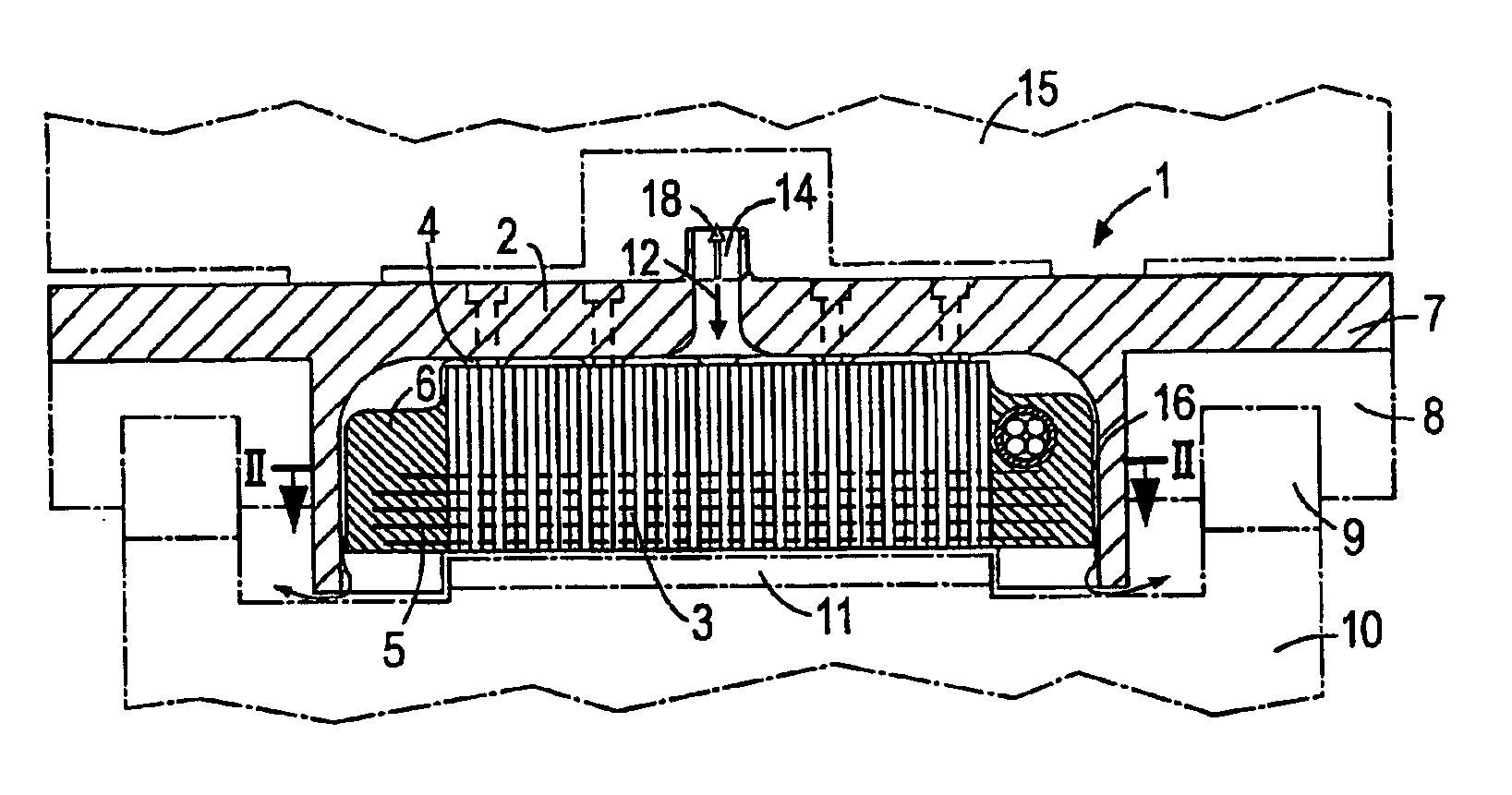
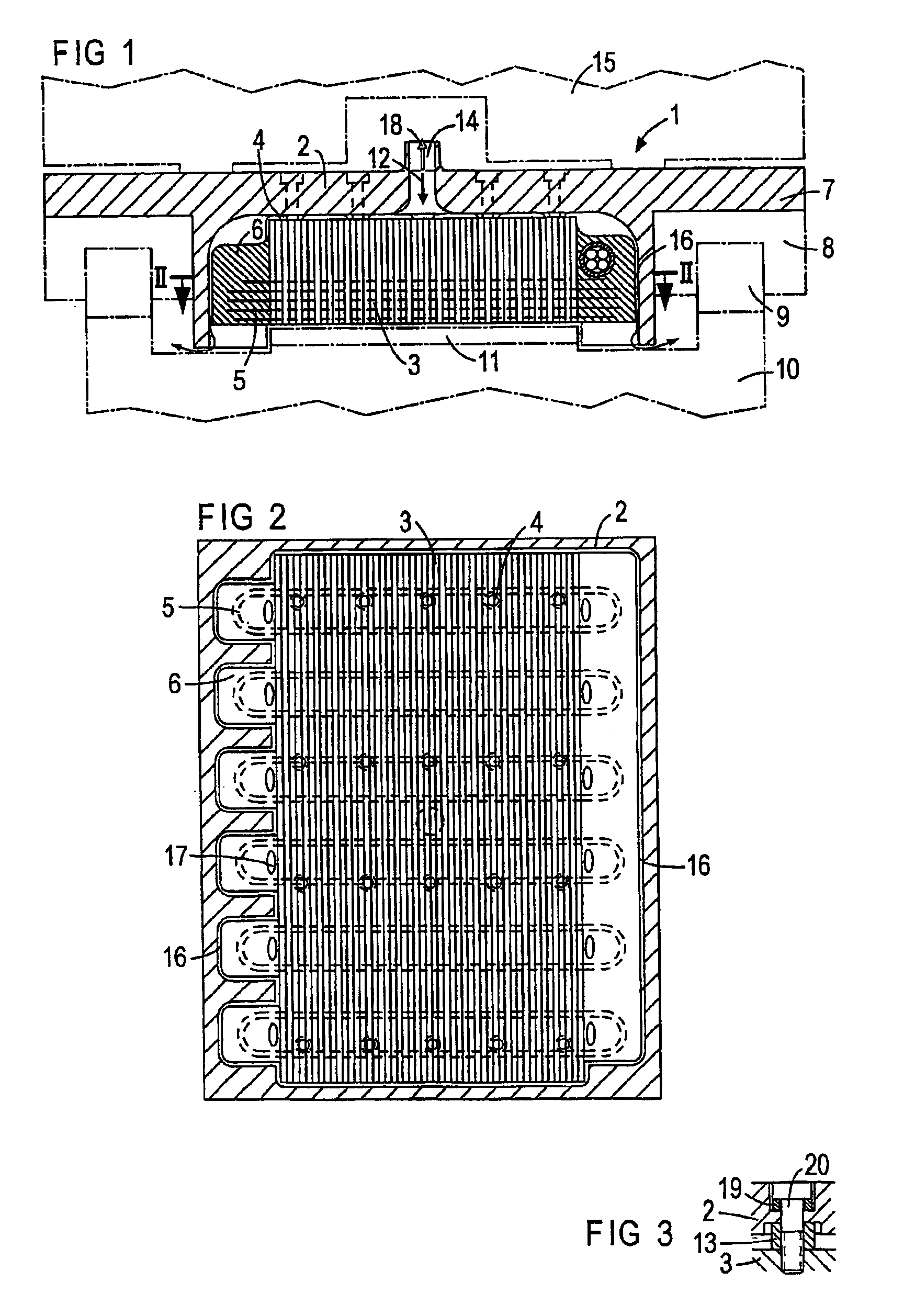
[0021]According to FIGS. 1 and 2, a coil unit 1 has a housing 2 to which an iron core 3 formed from slats is secured via support elements 4 embodied as support knuckles shaped as a single piece onto the housing 2. The iron core 3 is permanently linked with windings of electrical coils 5 by means of a cast compound 6. The housing 2 has laterally protruding flange-type projections 7 serving to secure linear guide elements 8. Said elements act in conjunction with corresponding guide rails 9 of a stationary guide track 10. Between the guide rails 9, said track has a magnetic track 11 consisting of permanent magnets arranged side by side in the direction of travel.

[0022]The housing 2 is open at the side facing the magnetic track 11 and, on the other sides, encloses the iron core 3 with the coils 5 with a narrow spacing. Said spacing is presented as a circumferential gap 16 whose width has been reduced to the fraction of half a millimeter. Together with the cast compound 6, the iron core ...


PUM


Abstract

The present invention is directed to a coil unit of a single-acting linear engine. The coil unit includes an iron core with coils that are linked with the iron core by way of a cast compound thereby forming a molded part. The molded part is enclosed by a housing having a narrow circumferential gap formed between the housing and the molded part. Through the gap, cooling air may flow or be blasted. The air extensively cools the iron core with the coils and thermally insulates the housing from the iron core and the coils.

Description

CROSS REFERENCE TO RELATED APPLICATIONS[0001]The present application is a continuation of International Application PCT / DE02 / 04307, filed Nov. 25, 2002, which designated the United States, and claims priority to German application DE 10158694.9, filed Nov. 29, 2001, the both of which are herein incorporated by reference.BACKGROUND OF THE INVENTION[0002]The invention relates to a coil unit of a linear motor with electromagnetic coils, having at least one iron core and having a housing which encloses said coils and iron core and which is open toward a magnetic track of the linear motor, with the iron core being permanently linked with the housing, the coils being secured in position by means of a cast compound and at least one cooling-air channel being provided within the housing.[0003]A coil unit of said type is known from, for instance, DE 19842384 A1. According to this, a primary motor section is accommodated in a housing called a bogie truck and is able to travel over a secondary ...

Claims


Application Information

Patent Timeline
IPC IPC(8): H02K41/02H02K9/04H02K41/03
CPCH02K41/031H02K9/04H02K41/02
Inventor ANDERSCH, WALTER
Owner SIEMENS AG
Why Eureka
Try Eureka