Plasma display panel drive apparatus and drive method

a technology of display panel and drive device, which is applied in the direction of instruments, computing, electric digital data processing, etc., can solve the problems of low supply capacity, low power efficiency, and tendency for discharge to start before the drive voltage, and achieve good power efficiency, high power efficiency, and great variation in intensity

Inactive Publication Date: 2005-07-26
PANASONIC CORP
View PDF17 Cites 11 Cited by
  • Summary
  • Abstract
  • Description
  • Claims
  • Application Information

AI Technical Summary

Benefits of technology

[0024]If the charge recovery period is made long, because sufficient charge recovery is achieved, the power efficiency is good and there is not a great variation in intensity related to the amount of load, although the peak intensity is low when compared to the case of making the charge recovery period short.
[0025]The present invention was made in consideration of the above-noted effect and, for the case of a relatively bright display screen that has a h...

Problems solved by technology

However, if the time constant of the LC resonant circuit is made large in order to achieve a sufficient recovery efficiency, the action of electrical charge recovery causes a loss of sharpness in the sustaining pulse applied to the scanning and common electrodes, so that there is a tendency for discharge to start before the drive voltage has risen completely.
If discharge occurs midway during electrical charge recovery, the discharge current is supplied from the LC resonant...

Method used


Image

  • Plasma display panel drive apparatus and drive method
  • Plasma display panel drive apparatus and drive method
  • Plasma display panel drive apparatus and drive method

Examples


first embodiment

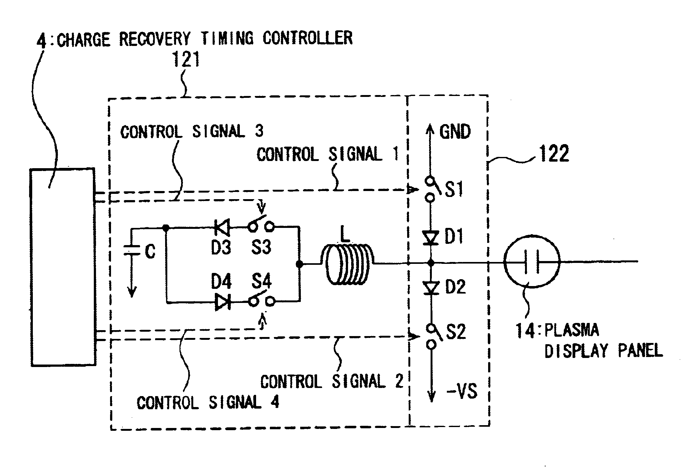
[0032]FIG. 1 shows a plasma display panel drive apparatus according to the present invention.

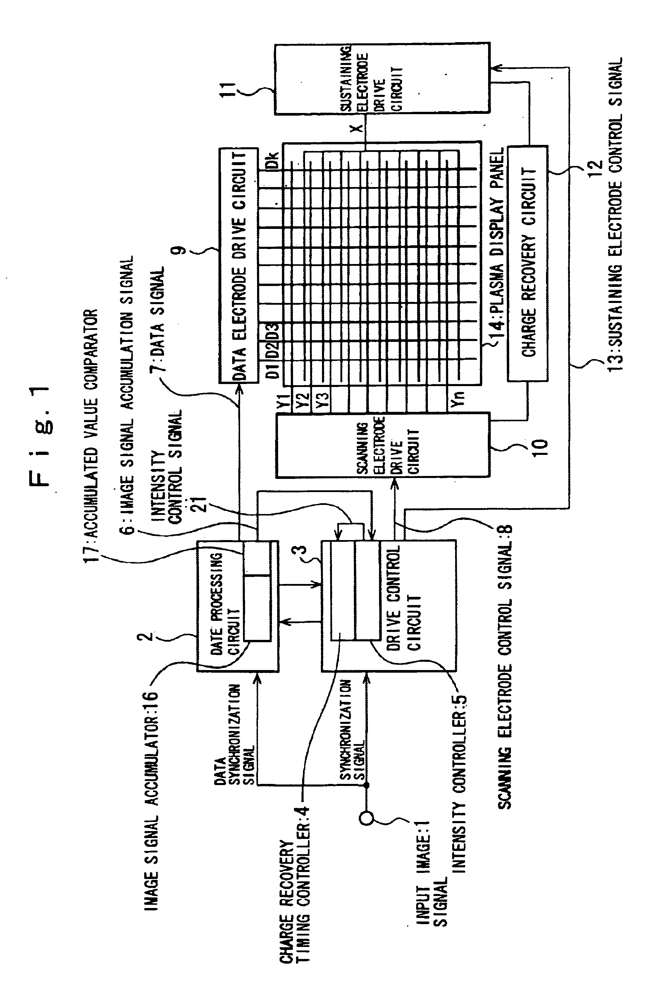
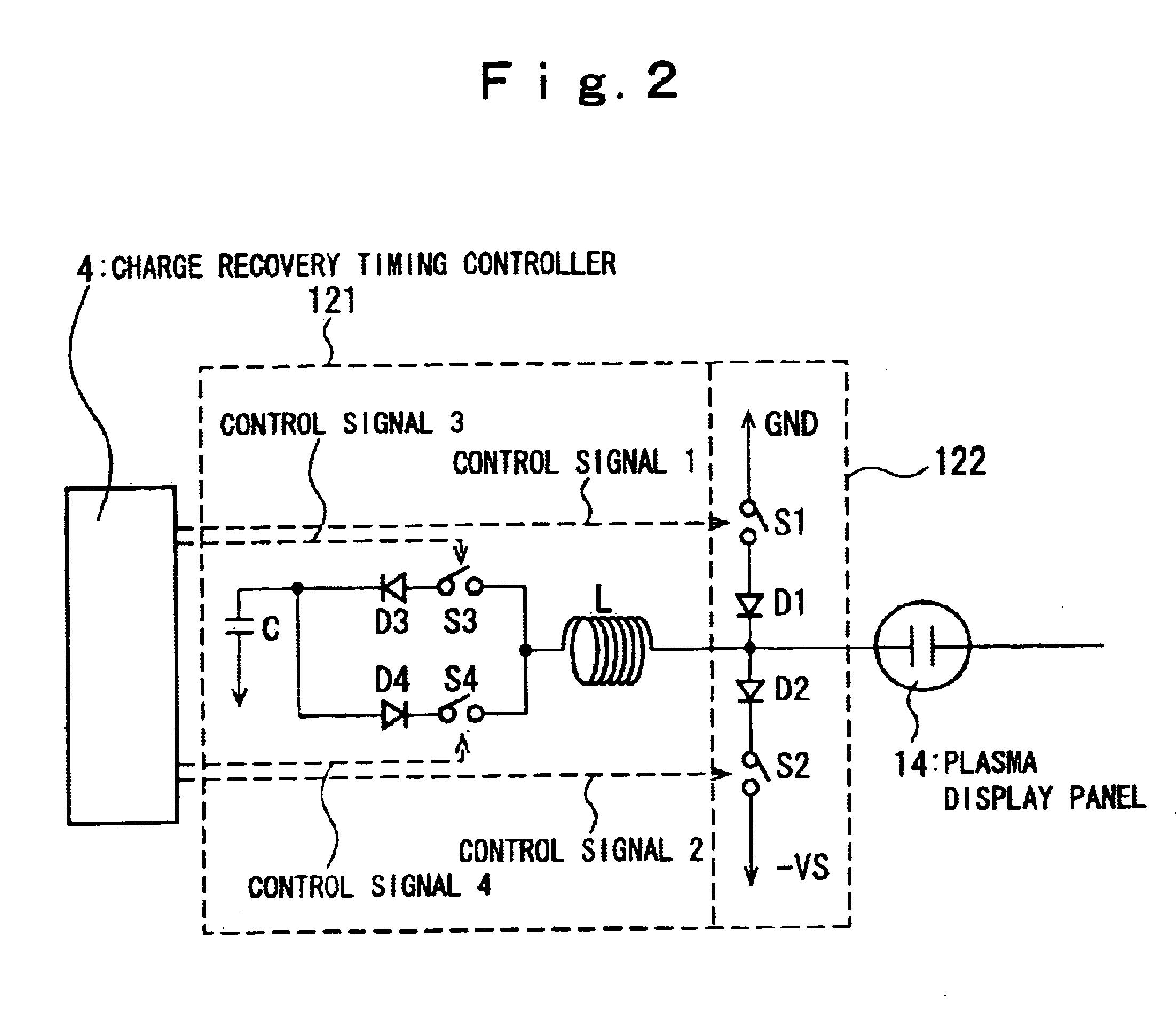
[0033]The plasma display panel drive apparatus shown in FIG. 1 comprises a plasma display panel 14, the electrical charge of which is recovered by the charge recovery circuit 12 and re-used, this drive apparatus has an image signal accumulator 16, for accumulating the intensity of each pixel of a plasma display panel for each frame or for each field of an image signal, an accumulated value comparator 17 for performing a comparison to determine whether an accumulated value detected by the image signal accumulator 16 is larger or smaller than a prescribed value, and a charge recovery timing controller 4 for the purpose of varying the charge recovery period T (refer to FIG. 3) from the time at which the charge recovery operation of the charge recovery circuit starts to the time of fixing at a sustaining potential or the ground potential, based on the comparison results of the accumulated value ...

second embodiment

[0054]FIG. 5 is a block diagram showing the present invention.

[0055]In the second embodiment, even if image signal accumulation signal indicates low value, for an image having a small difference in intensity in the intensity distribution within the screen, control is performed so as to give priority to achieving gray-scale characteristics, as opposed to making a display giving priority to achieving peak intensity. It is therefore possible with the second embodiment to achieve a display with superior gray-scale characteristics, even in the case of a overall dark display screen.

[0056]In this configuration, first intensity data of the RGB cells for each pixel is compared to determine if it is higher or lower than a reference value, the number of pixels for which the intensity is higher than the above-noted value is then counted for each frame or each field, after which, in the case in which if there is a large number of pixels having an intensity higher than the above-noted reference v...


PUM


Abstract

A drive apparatus for a plasma display panel useing a charge recovery circuit 12 that re-uses a recovered electrical charge, the drive apparatus comprising: a brightness detection means 16, 17 for detecting a brightness so as to obtain screen brightness information; and a charge recovery timing control means 4 for controlling a charge recovery period T from a time at which a charge recovery operation of the charge recovery circuit 12 starts to a time of fixing to a sustaining potential or a ground potential, wherein the charge recovery timing control means 4 controls the charge recovery period of the charge recovery circuit 4 in response to the brightness information obtained by the brightness detection means 16, 17.

Description

BACKGROUND OF THE INVENTION[0001]1. Field of the Invention[0002]The present invention relates to a plasma display panel drive apparatus and to a drive method therefor, and more particularly to a plasma display panel drive apparatus with improved display quality and a drive method therefor.[0003]2. Related Art[0004]In a plasma display panel, a charge recovery circuit is provided to improve the power efficiency.[0005]A basic approach to charge recovery by the charge recovery circuit is that which focuses on the functioning of an AC-type plasma display as a capacitor after the completion of discharge, wherein the electrical charge accumulated on the panel is extracted using an LC resonant circuit, this being used when discharging again, thereby reducing the reactive power and improving the power efficiency.[0006]However, if the time constant of the LC resonant circuit is made large in order to achieve a sufficient recovery efficiency, the action of electrical charge recovery causes a l...

Claims


Application Information

Patent Timeline
IPC IPC(8): G09G3/28G09G3/288G09G3/20G09G3/291G09G3/294G09G3/296
CPCG09G3/2007G09G3/294G09G3/2965G09G2310/066G09G2320/0626G09G2320/066G09G2330/024G09G2360/16
Inventor WATANABE, TAKUYA
Owner PANASONIC CORP
Why Eureka
Try Eureka