Pressure relief valve with small dimensions

a pressure relief valve and small size technology, applied in the field of pressure relief valves for packaging containers, can solve the problems high opening pressure of valves, and differences in the distance between the recess and the valve diaphragm, so as to reduce the dimensions of the pressure relief valve and reduce the cost of materials. , the effect of high vacuum tightness

Inactive Publication Date: 2012-02-23
ROBERT BOSCH GMBH
View PDF6 Cites 4 Cited by
  • Summary
  • Abstract
  • Description
  • Claims
  • Application Information

AI Technical Summary

Benefits of technology

[0004]In contrast, the pressure relief valve according to the invention, has the advantage that it opens even at very small excess pressures above ambient pressure of less than 1000 Pa (10 mbar), more particularly less than 500 Pa (5 mbar) and has a very high vacuum tightness at a pressure difference of over 60000 Pa between the inside and the outside of the packaging. Moreover, the pressure relief valve according to the invention is of very small size, enabling it to be attached very inconspicuously to the package. On the one hand, reducing the dimensions of the pressure relief valve reduces the cost of materials and, more particularly, allows greater variation in the positioning of the pressure relief valve on the package. Furthermore, it is possible to achieve improved application of the pressure relief valve to the package since the sealing forces to be applied are smaller owing to the smaller sealing area. In addition, the pressure relief valve has just two main components, namely a main body and a diaphragm. According to the invention, this is achieved by virtue of the fact that...

Problems solved by technology

In practice, however, the two above-mentioned aims are in conflict since, on the one hand, the pressure for opening the valve should only be low and, on the other hand, high vacuum tightness should b...

Method used


Image

  • Pressure relief valve with small dimensions
  • Pressure relief valve with small dimensions
  • Pressure relief valve with small dimensions

Examples


Embodiment Construction

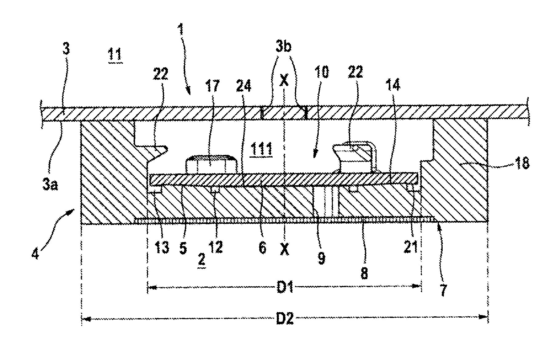
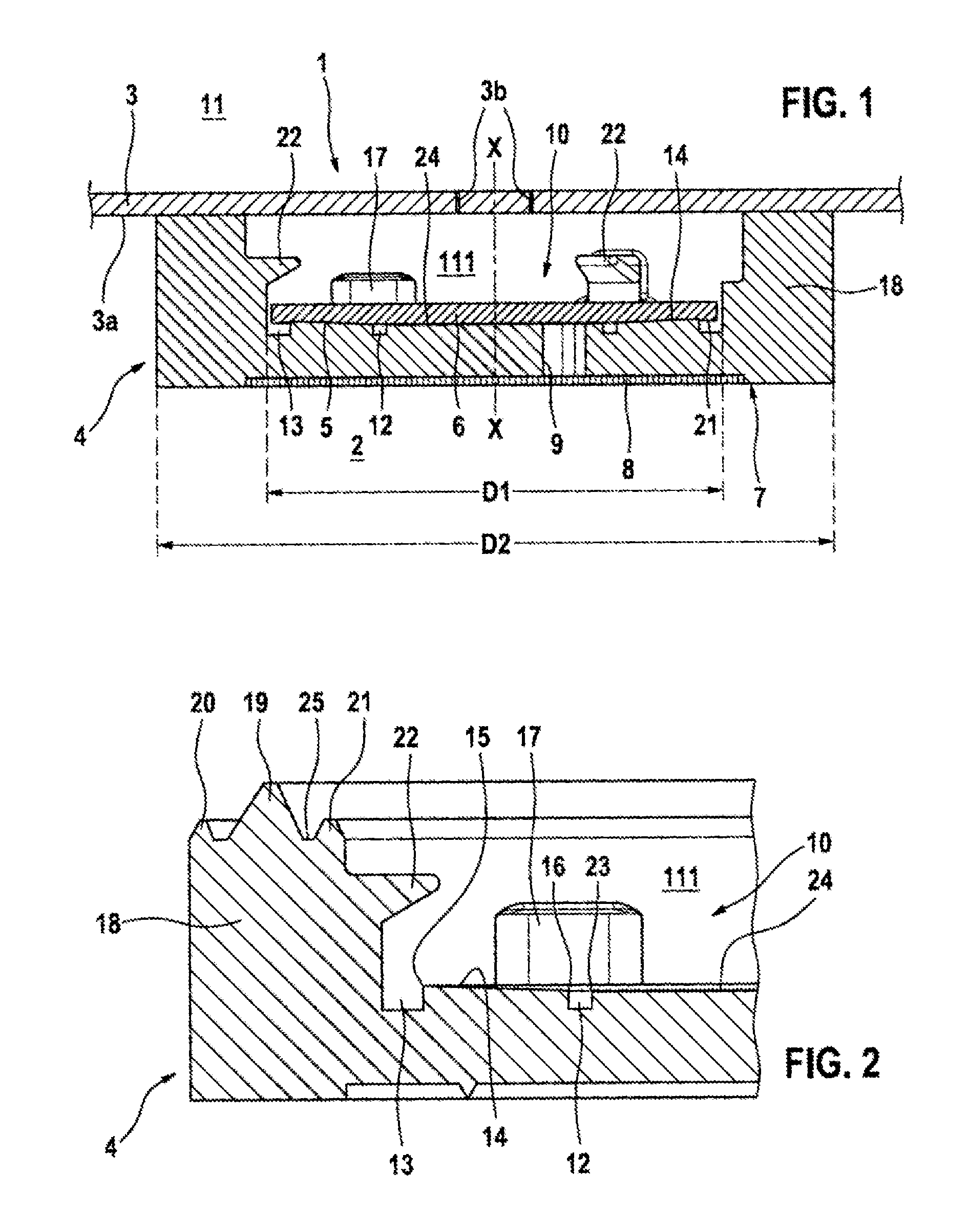
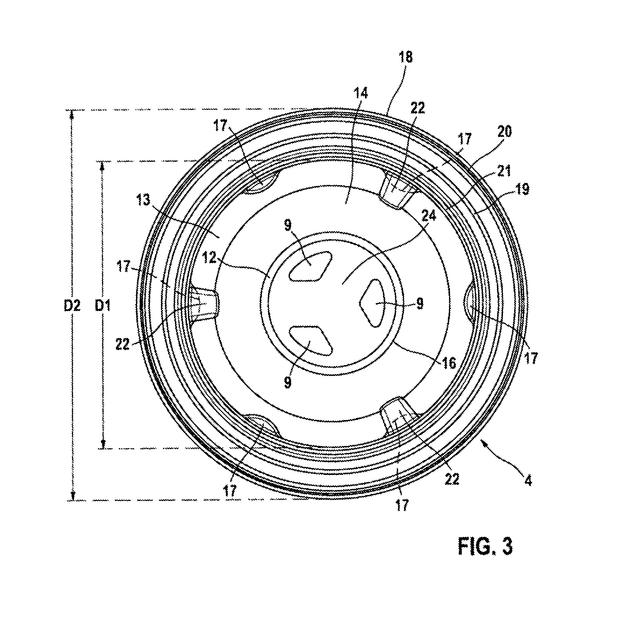
[0020]A pressure relief valve 1 in accordance with a first preferred illustrative embodiment of the invention is described in detail below with reference to FIGS. 1 to 3.

[0021]As can be seen from FIG. 1, the pressure relief valve 1 according to the invention comprises a main body 4 and a diaphragm 6. The pressure relief valve 1 is fixed on an inner side 3a of a package 3 by means of a sealing operation. Openings 3b, under which the pressure relief valve 1 is secured, are provided in the package 3. In FIG. 1, an interior space in the package 3 is denoted by the reference sign 2, and an exterior space around the package (surroundings) is denoted by the reference sign 11. Here, the pressure relief valve 1 has the function of releasing any excess pressure that arises in the package 3 to the outer side 11 and to seal off any vacuum prevailing in the package 3 from the outer side.

[0022]The main body 4 is designed to be cylindrical or slightly conical and relatively short and comprises a p...


PUM


Abstract

The invention relates to a pressure relief valve for a packaging container (3), comprising a base body (4) with at least one through opening (9, 29), a sealing surface (14) and a peripheral region (18), wherein the peripheral region (18) may be sealably connected to an inner surface (3a) of the packaging container (3), the sealing surface (14) having an inwardly tapering form and a flexible membrane (6), in contact with the sealing surface (14) of the base body (4) to generate a sealing effect. The membrane (6) covers the through opening (9), a fluid (5) is arranged between the sealing surface (14) and the membrane (6), wherein a recess (10) is formed in the base body (4) to accommodate thee membrane (6). The recess (10) has a first diameter (D1), between 70 and 80% of a total diameter (D2) of the base body (4).

Description

BACKGROUND OF THE INVENTION[0001]The present invention relates to a pressure relief valve for a packaging container, which valve has very small dimensions.[0002]Various embodiments of pressure relief valves for packaging containers are known from the prior art. The use of valves, especially on flexible packages for foodstuffs, has already been implemented by a large number of technical variants. A principal requirement on valves of this kind is that they should permit only slight excess pressures in the package through appropriate opening and otherwise should reliably prevent the penetration of ambient air. In this context, the penetration of ambient air must be prevented even when the pressure in the package is very low. In practice, however, the two above-mentioned aims are in conflict since, on the one hand, the pressure for opening the valve should only be low and, on the other hand, high vacuum tightness should be provided. Valves which have a high vacuum tightness therefore al...

Claims


Application Information

Patent Timeline
IPC IPC(8): F16K15/14
CPCB65D77/225F16K99/0001F16K17/18F16K15/141Y10T137/7879
Inventor STOTKIEWITZ, HERBERTSTADEL, HANS-PETERHAAK, JUERGEN
Owner ROBERT BOSCH GMBH
Why Eureka
Try Eureka