Optical switch

a technology of optical switch and optical resonator, which is applied in the field of optical switch, can solve the problems of insufficient switching behavior of the conventional switch of the above-cited us patent publication, and achieve the effects of reducing the number of optical resonators, and improving the quality factor q of the optical resonator

Active Publication Date: 2007-01-25
IBM CORP
View PDF10 Cites 5 Cited by
  • Summary
  • Abstract
  • Description
  • Claims
  • Application Information

AI Technical Summary

Benefits of technology

[0010] When the reflecting interfaces at least substantially enclose the optical resonator, light is reflected more completely and the energy of the light is enclosed in the optical resonator more efficiently. Thus, the quality factor Q of the optical resonator is increased and the switching behaviour of the optical switch is more pronounced. Therefore, it is possible to control the switch with a lower intensity or power of the control signal and / or with lower modulations of the intensity of the control signal. Alternatively, for the same intensity and modulation of intensity of the control signal, a lower refractive index contrast and / or a less pronounced non-linearity of the optical resonator material is required. With the lower requirements to the non-linearity, a broader variety of non-linear materials can be used. All these aspects considered, the present invention provides a faster, more power-efficient and cheaper optical switch.

Problems solved by technology

For many applications, the switching behavior of the conventional switch of the above-cited US patent publication may be insufficient.

Method used


Image

  • Optical switch
  • Optical switch
  • Optical switch

Examples


first embodiment

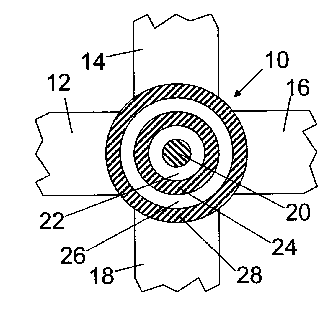
[0020]FIG. 1 is a schematic top view of an optical switch according to the present invention. The optical switch comprises an optical resonator 10 and optical waveguides 12, 14, 16, 18, optically coupled to the optical resonator 10. In the present embodiment, the four optical waveguides 12, 14, 16, 18 coupled to the optical resonator 10 are equivalent. In particular, the whole switch comprises a fourfold symmetry axis perpendicular to the drawing plane and the width of all waveguides 12, 14, 16, 18 are equal.

[0021] Also, without loss of generality, the waveguides will subsequently be referred to as a first input optical waveguide 12 for guiding a first optical signal to the optical resonator 10, a second input optical waveguide 14 for guiding a second optical signal to the optical resonator 10, a first output optical waveguide 16 for guiding a third optical signal from the optical resonator 10 and a second output optical waveguide 18 for guiding a fourth optical signal from the opti...

third embodiment

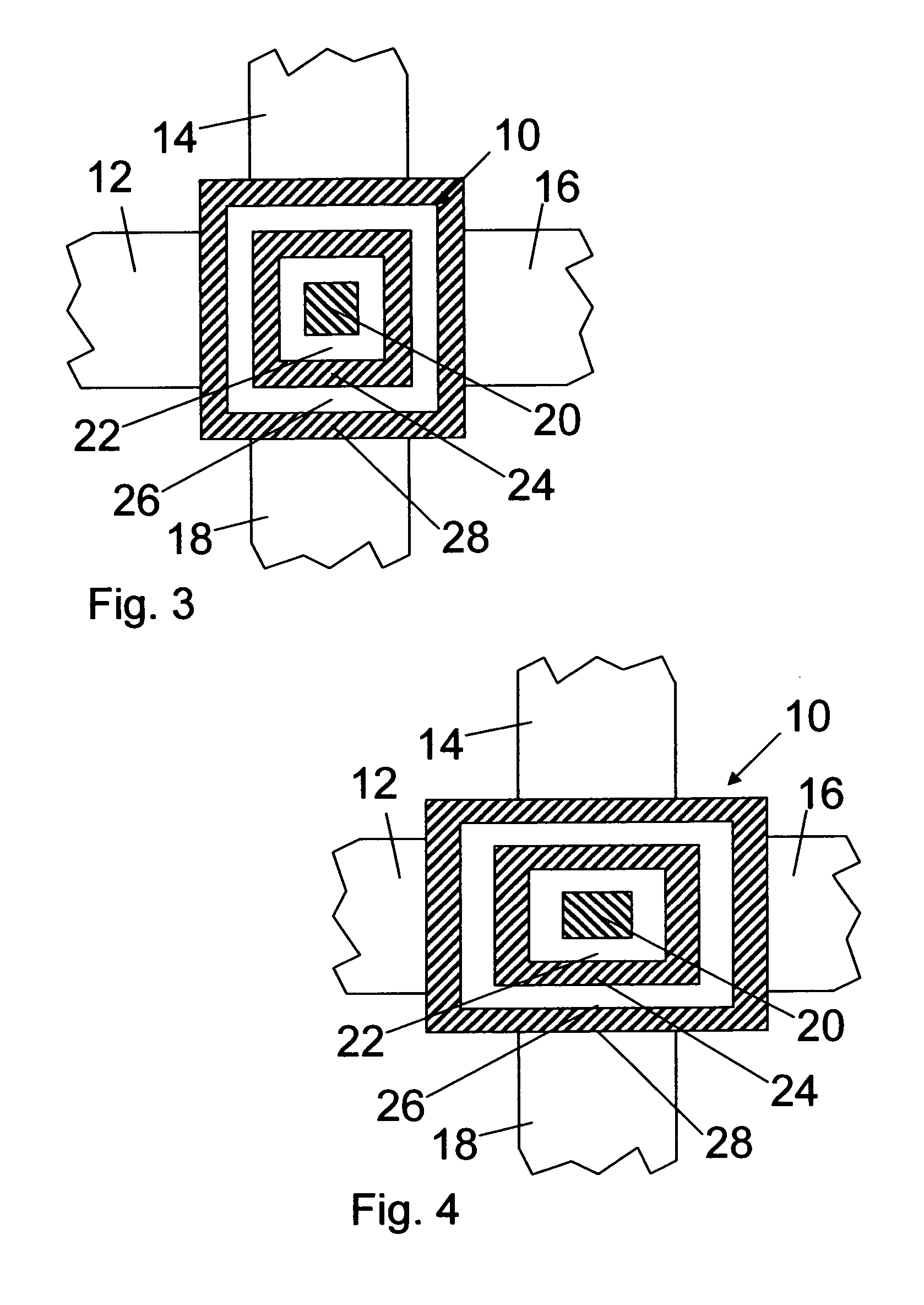
[0044]FIG. 6 is a schematic top view of an optical switch with a square-like resonator structure. This embodiment differs from the third embodiment described above with reference to FIG. 3 in that the second and fourth quadratic frames 24, 28 of the optical resonator 10 are subdivided into segments 241, 242, 243, 244, or 281, 282, 283, 284, respectively, by smaller gaps 30.

[0045] The gaps 30 are positioned at the corners of the quadratic frames 24, 28 and, hence, between the optical waveguide 12, 14, 16, 18. Thereby, the segments 241, 242, 243, 244, 281, 282, 283, 284 are straight strips. The segments may be rectangular as displayed in FIG. 6 or shaped like trapezoids.

[0046] The gaps 30 only slightly reduce the quality factor Q of the optical resonators 10 displayed in FIGS. 5 and 6. Furthermore, the resonator modes or eigenmodes of the optical resonator 10 are only slightly influenced by the smaller gaps 30. The gaps 30 may, for example, be used for stabilizing the orthogonality o...


PUM


Abstract

An optical switch, comprising an optical resonator, a first input optical waveguide optically coupled to the optical resonator for guiding a first optical signal to the optical resonator; a second input optical waveguide optically coupled to the optical resonator for guiding a second optical signal to the optical resonator; and an output optical waveguide optically coupled to the optical resonator for guiding a third optical signal from the optical resonator, wherein the optical resonator has a first region and at least one separate second region made of different materials, at least one of which is non-linear to cause different resonance frequencies of the optical resonator for different intensities of light.

Description

FIELD OF THE INVENTION [0001] The present invention refers to an optical switch, wherein an optical control signal switches another optical signal. Background of the Invention [0002] In almost all fields of information technology, the data rates increase continuously. The transfer of data as electrical signals via copper wires comes to physical limits. Much higher data rates can be transferred as optical signals via fibre optic cables or other optical waveguides. [0003] Optical signals can be switched by means of electro-optical switches. However, for many applications all-optical switches are required and / or advantageous. In an all-optical switch, a first signal carrying information encoded in modulation of the intensity or power is switched by a second optical signal. When the intensity of the second signal is higher, the first signal is transmitted and when the intensity of the second signal is lower, the first signal is blocked, or vice versa. [0004] US patent publication number...

Claims


Application Information

Patent Timeline
Patent Type & Authority Applications(United States)
IPC IPC(8): G02B6/26
CPCG02F1/3515G02F2203/15G02F2001/3509G02F2001/3507G02F1/3509G02F1/3507
Inventor MAHRT, RAINER F.MOLL, NIKOLAJ
Owner IBM CORP
Why Eureka
Try Eureka