Method and apparatus for generating structural data from laser reflectance images

a technology of laser reflectance and structural data, applied in the direction of reradiation, distance measurement, instruments, etc., can solve the problems of plant inability to shut down, loss of productivity, and insufficient design drawings, so as to reduce computing resources, reduce the cost of generating required information, and improve the effect of efficiency

Inactive Publication Date: 2005-07-26
QUANTAPOINT
View PDF8 Cites 64 Cited by
  • Summary
  • Abstract
  • Description
  • Claims
  • Application Information

AI Technical Summary

Benefits of technology

The present invention is a scanning laser camera that can collect data and generate a point cloud and a high-resolution reflectance image simultaneously. This data can be easily manipulated by a human operator without the need for 3D modeling. The invention is unique in that it works exclusively with a 2D representation of a 3D database, making it faster and more cost-effective than other techniques. The data collected is more complete and accurate, and can be easily manipulated by workers unskilled in 3D data manipulation. This invention will result in lower engineering costs, lower construction costs, and a more accurate, better-documented infrastructure in the US.

Problems solved by technology

The technical problem addressed in this patent is the need for a faster, safer, and more accurate method of measuring the existing conditions of an operating plant, as traditional methods such as manual, traditional survey, and photogrammetry are slow, dangerous, inaccurate, and expensive. The invention proposes a lidar device with unique properties that can generate useful structural data faster and with a different paradigm than other lidar systems.

Method used


Image

  • Method and apparatus for generating structural data from laser reflectance images
  • Method and apparatus for generating structural data from laser reflectance images
  • Method and apparatus for generating structural data from laser reflectance images

Examples


second embodiment

[0055]A second embodiment currently in use is creation of a displayable reflectance image 270 using the TIFF graphics format. Additional industry standard and nonstandard formats can be used with no difference in operation to the fundamental concepts encapsulated in the present invention.

third embodiment

[0056]the reflectance image 270 involves merging the reflectance measurements 50 with color intensity data 280 captured by a traditional or digital photographic camera. The resulting image is a colorized reflectance image 290 and is displayed in the same industry standard formats as the gray-scale images.

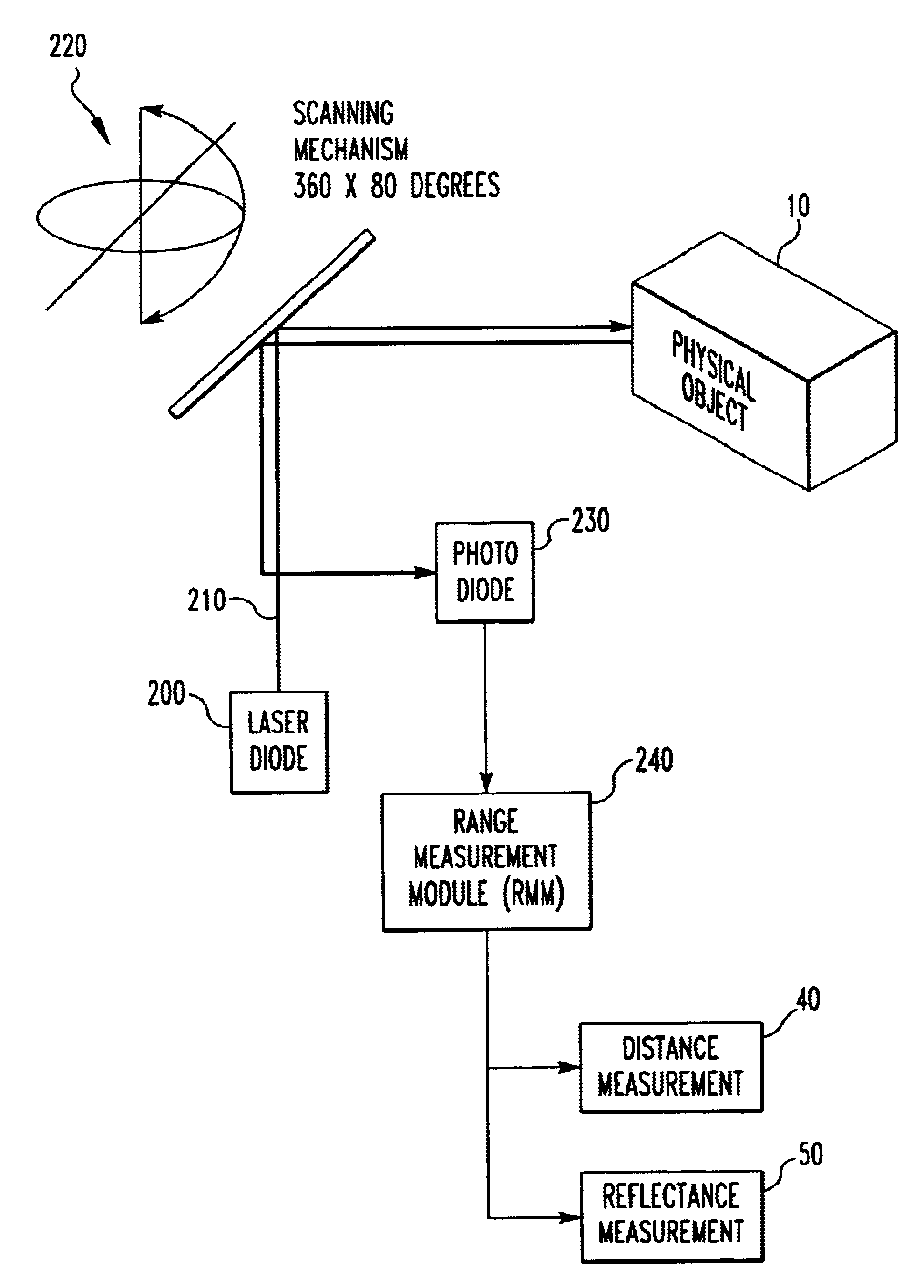
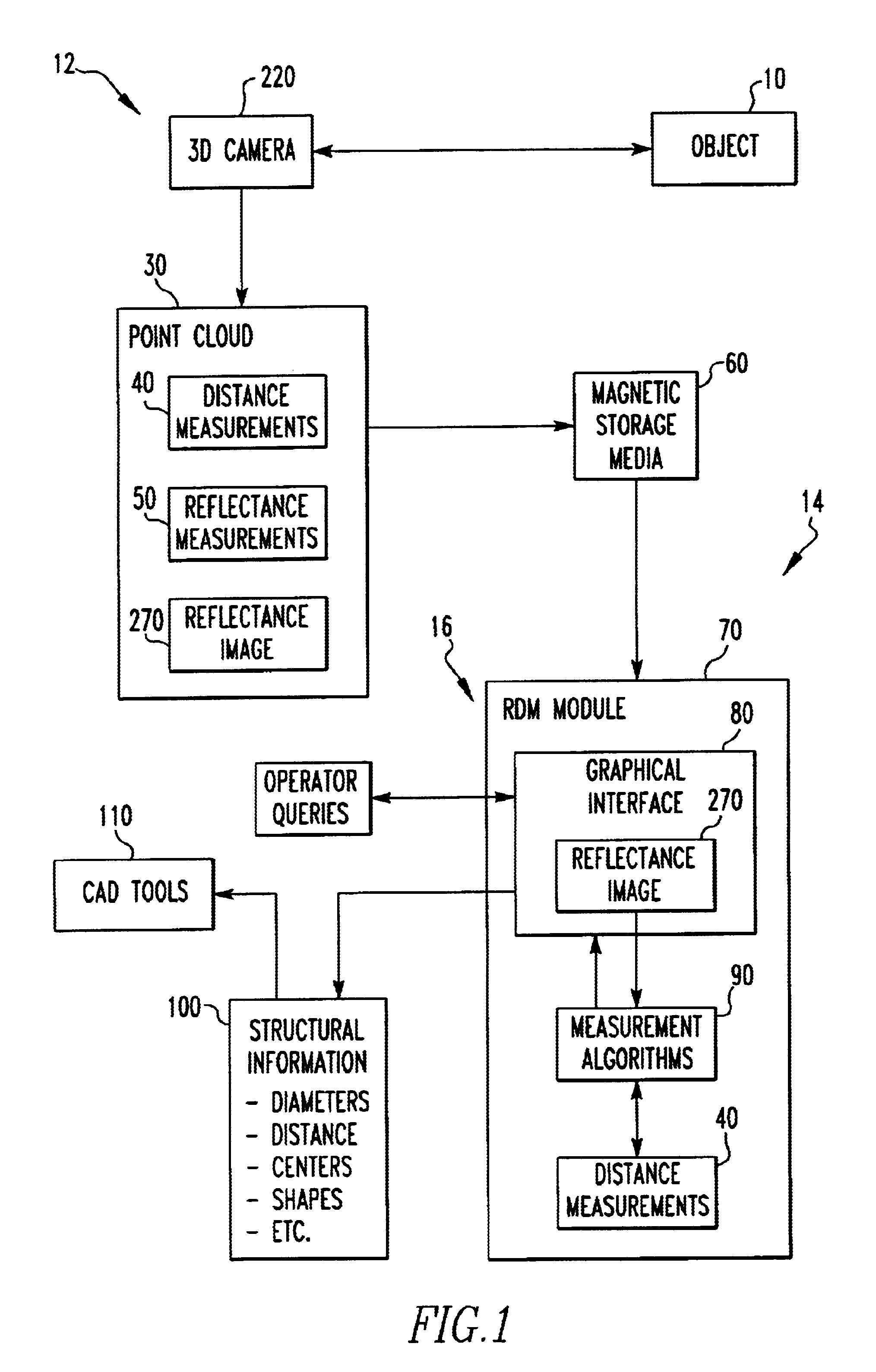
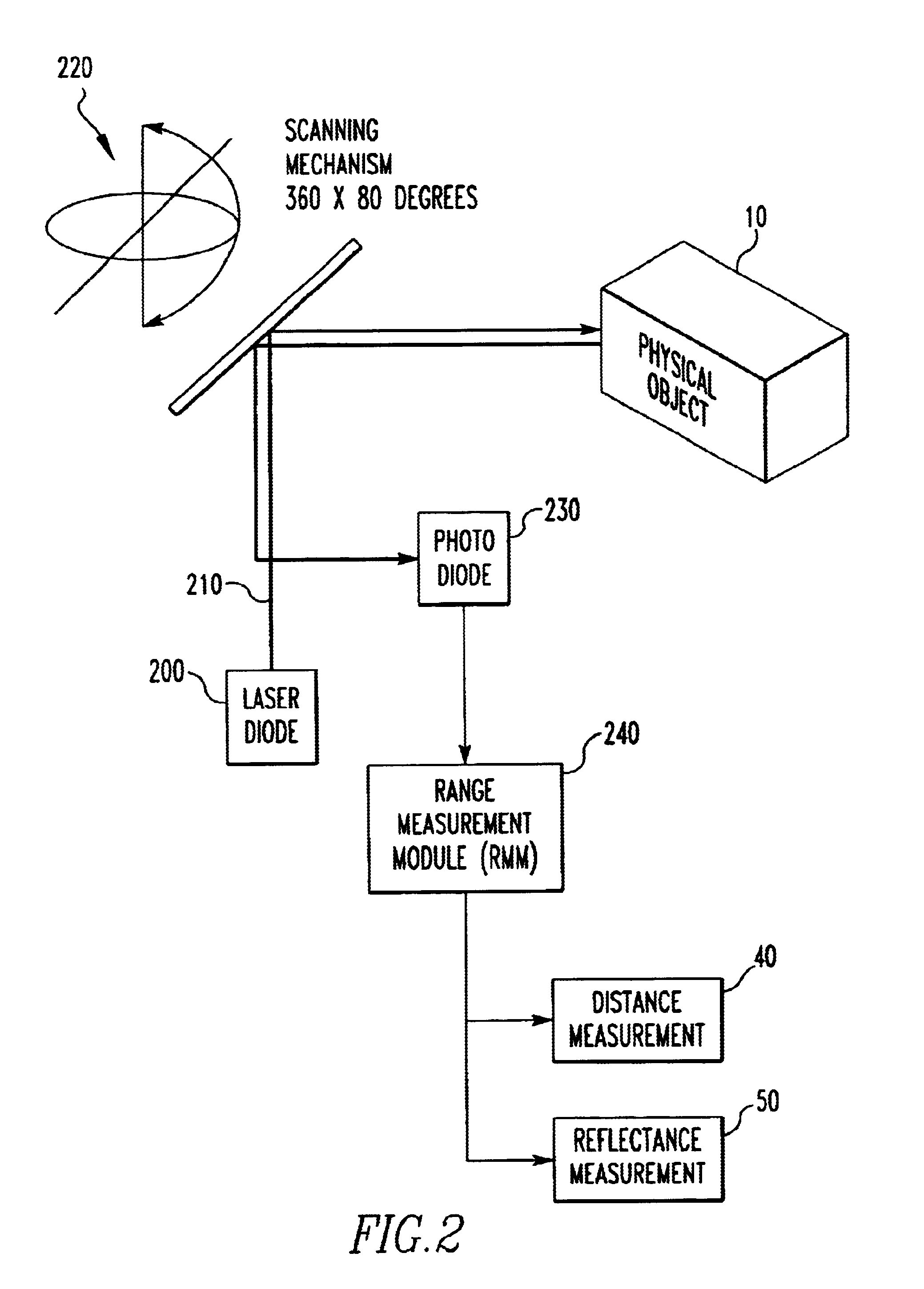
[0057]Collectively, the distance measurements 40 and the reflectance measurements 50 create a point cloud 30. Each point in the point cloud 30 corresponds exactly to one point in the reflectance image 270.

[0058]Other embodiments of a 3D camera can be used with the present invention assuming that the other embodiments include an ability to generate spatially dense distance data, reflectance measurements 50, and a known correspondence between the 2D reflectance data and the 3D distance measurement data.

first embodiment

[0059]In the present invention, the magnetic media is comprised of an industry standard hard drive that is connected to the 3D camera via a SCSI bus. Alternate bus schemes can also be used without any change in the core invention. These can include Ethernet, parallel, Firewire, or any other bus architecture that can move binary data from a computing module to a magnetic storage medium. The hard drive stores distance measurements 40 and reflectance measurements 50 in a binary data file.

[0060]When an operator requests data in the RDM module, the binary data file is copied from the magnetic media to the RAM resident on the PC running the RDM module, typically through an Ethernet link, but also through a local bus resident on the PC if the data is stored on a local hard drive as opposed to a networked hard drive.

[0061]In a second embodiment of the invention, only the reflectance component of the data is loaded into the RDM module. When an operator requests a measurement of an object, on...


PUM


Abstract

An apparatus for generating structural data of a structure. The apparatus includes a scanning laser range finder that produces reflectance data of the structure. The apparatus includes a memory which stores the reflectance data. The apparatus includes means for determining desired spatial relationships of the structure from the reflectance data. A method for generating structural data of a structure. The method includes the steps of producing reflectance data of the structure with a scanning laser range finder. There is the step of storing the reflectance data in a memory. There is the step of determining desired spatial relationships of the structure from the reflectance data.

Description


Claims


Application Information

Patent Timeline
Owner QUANTAPOINT
Why Eureka
Try Eureka