Fly-back converter with constant pulse width and variable duty cycle using a capacitor in control circuit

a control circuit and capacitor technology, applied in the direction of electric variable regulation, process and machine control, instruments, etc., can solve the problems of large switching loss, different types of loss in switching power supply, and type of loss in switching loss which occurs, and achieve low switching loss.

Inactive Publication Date: 2005-07-26
MURATA MFG CO LTD
View PDF5 Cites 34 Cited by
  • Summary
  • Abstract
  • Description
  • Claims
  • Application Information

AI Technical Summary

Benefits of technology

[0007]In order to overcome the above-described problems, preferred embodiments of the present invention provide a switching power supply having low switching loss without producing problems associated with intermittent oscillation or an increase in output ripple during operation under a low load condition, and an electronic apparatus including such a novel switching power supply.

Problems solved by technology

Various types of loss occur in the switching power supply.
One type of loss is a switching loss which occurs each time a switching device switches.
Because the switching loss occurs each time the switching device switches, if the frequency increases with decreasing load, a large switching loss occurs.
Thus, the switching loss is a major component of the loss of the switching power supply when the load is within a low range.
When the load is very low, intermittent oscillation may occurs, which causes an increase in output ripple or noise that is generated.
However, in the switching power supply disclosed in Japanese Unexamined Patent Application Publication No. 2001-16849, the signal which turns the switching device on is blocked to prevent the turning-on of the switching device only when the output voltage is greater than a set value, and thus, the off-period of the switching device and the switching frequency are not constant even under a static load condition.
Therefore, the problems associated with the increase in the output ripple and noise are not adequately solved.

Method used


Image

  • Fly-back converter with constant pulse width and variable duty cycle using a capacitor in control circuit
  • Fly-back converter with constant pulse width and variable duty cycle using a capacitor in control circuit
  • Fly-back converter with constant pulse width and variable duty cycle using a capacitor in control circuit

Examples


Embodiment Construction

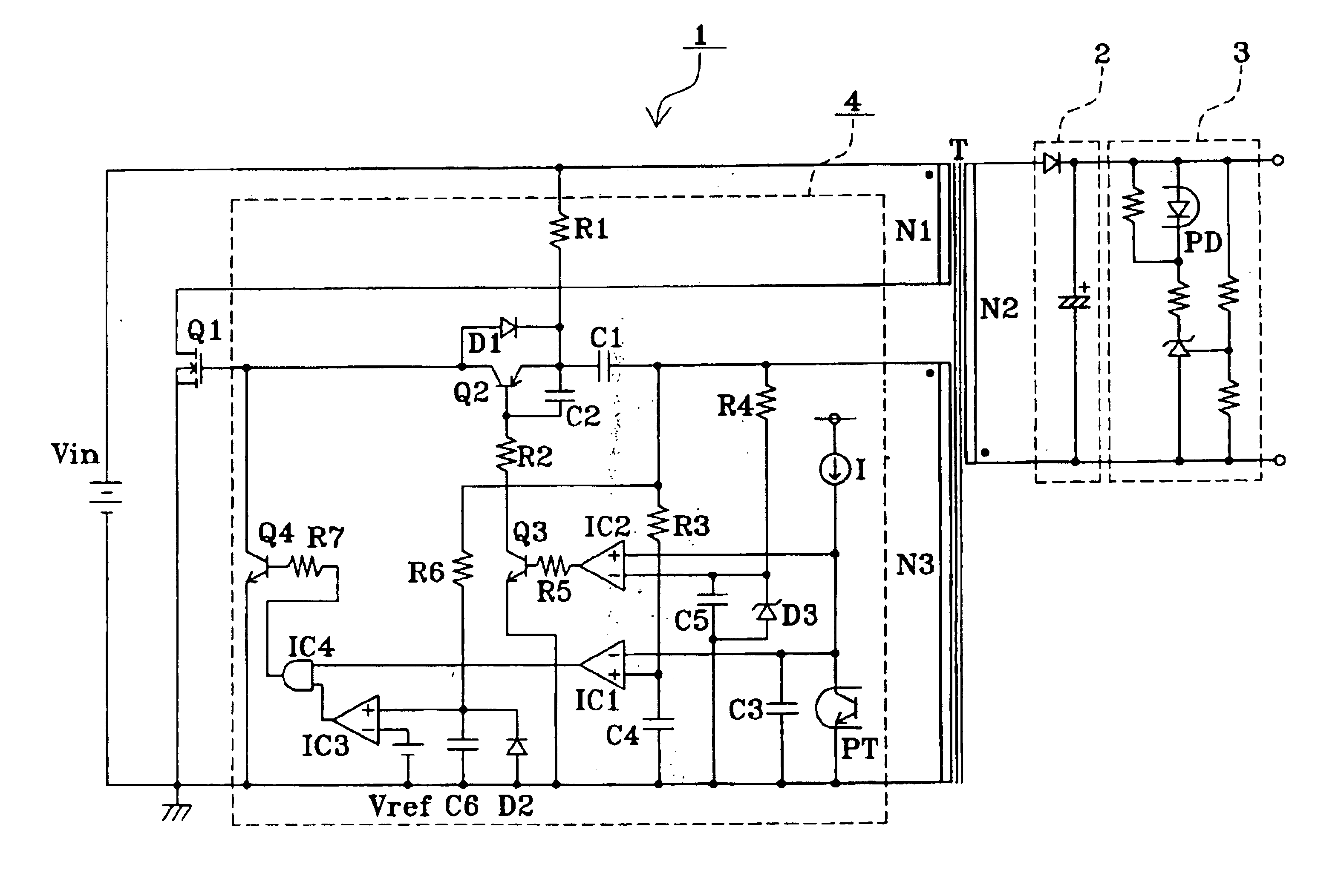
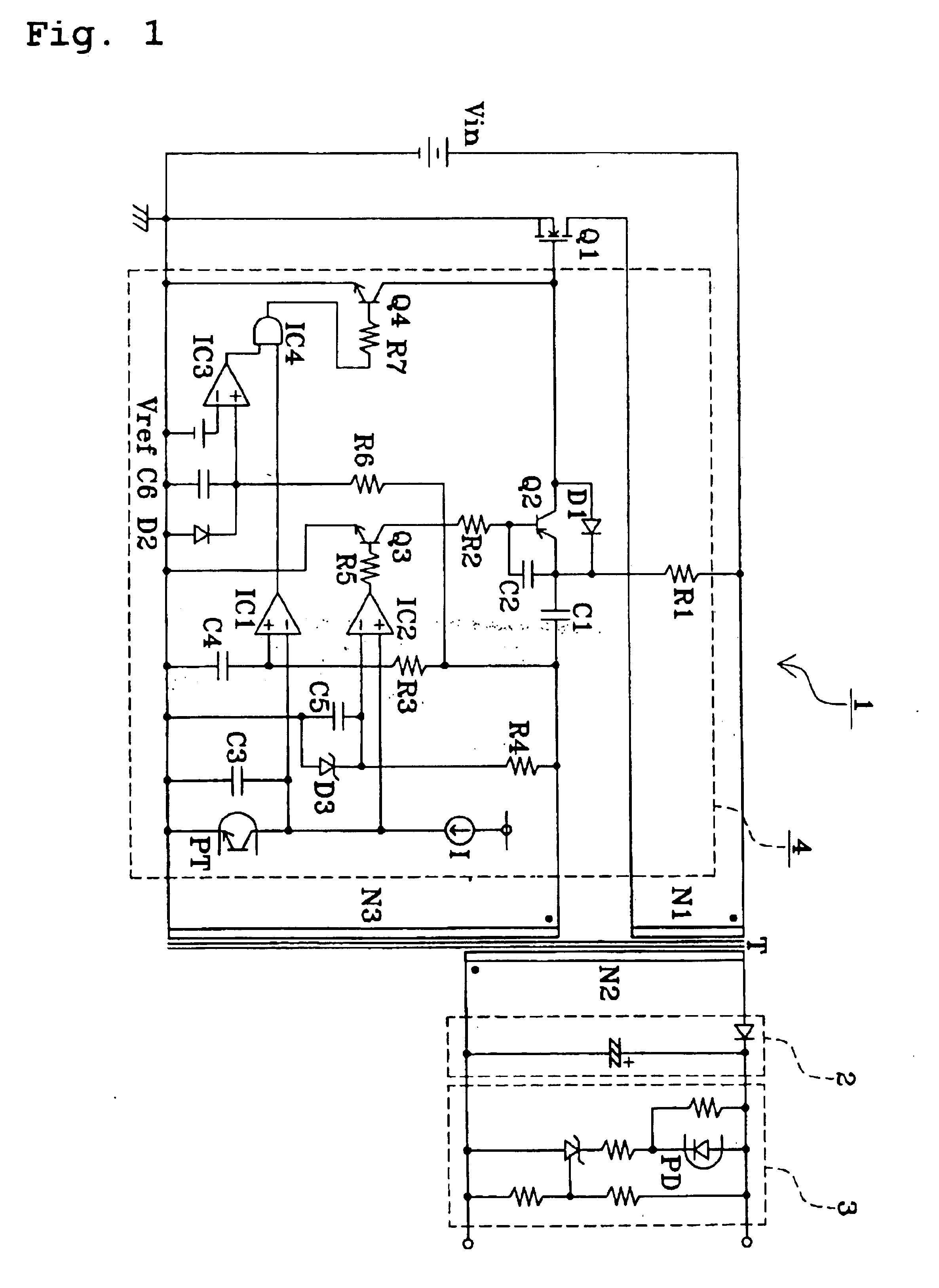
[0027]FIG. 1 is a circuit diagram of a switching power supply according to a preferred embodiment of the present invention. As shown in FIG. 1, the switching power supply 1 includes a transformer T including a primary winding N1, a secondary winding N2, and a feedback winding N3, a DC power supply Vin and a MOSFET functioning as a switching device Q1, both connected in series to the primary winding N1, a rectifying and smoothing circuit 2 connected to the secondary winding N2, an output voltage detecting circuit 3 connected to the rectifying and smoothing circuit 2, and a control circuit 4 provided between the feedback winding N3 and a gate serving as a control terminal of the switching device Q1. The output voltage detecting circuit 3 includes a light emitting diode PD defining one element of a photocoupler for outputting a feedback signal to the control circuit 4, wherein the photocoupler is connected such that when the output voltage increases due to a reduction in load, the inte...


PUM


Abstract

A switching power supply includes a control circuit disposed between a feedback winding and a switching device. The control circuit includes an on-period control circuit that, in an operation under a non-low load condition, controls an on-period of the switching device such that the on-period decreases with decreasing load, a minimum on-period setting circuit that disables the on-period control circuit in an operation under a low load condition so that the on-period of the switching device does not become shorter than a predetermined minimum on-period, and an off-period control circuit that controls an off-period of the switching device in the operation under the low load condition such that the off-period increases with decreasing load. As a result, the output voltage is maintained at a constant value in accordance with a feedback signal.

Description

BACKGROUND OF THE INVENTION[0001]1. Field of the Invention[0002]The present invention relates to a switching power supply and an electronic apparatus including a switching power supply, and more particularly, to a switching power supply that operates with low loss even under a low load condition, and an electronic apparatus including a switching power supply.[0003]2. Description of the Related Art[0004]In switching power supplies such as an RCC switching power supply, the switching frequency changes depending upon whether a load is low or high. When the load is high, the on-period and the off-period are both increased, and thus the switching frequency decreases. On the other hand, when the load is low, the on-period and the off-period are both decreased, and thus, the switching frequency increases. Various types of loss occur in the switching power supply. One type of loss is a switching loss which occurs each time a switching device switches. Because the switching loss occurs each ...

Claims


Application Information

Patent Timeline
Patent Type & Authority Patents(United States)
IPC IPC(8): H02M3/338H02M3/24H02M3/28
CPCH02M3/3385H02M2001/0032Y02B70/16Y02B70/10H02M1/0032
Inventor NISHIDA, AKIOTAKEMURA, HIROSHI
Owner MURATA MFG CO LTD
Why Eureka
Try Eureka