Light emission control system for a flash device

a control system and flash technology, applied in exposure control, optical radiation measurement, instruments, etc., can solve the problems of inability to obtain sufficient photometric output through ttl direct photometering system, inability to photometer the entire photometering area by a single preliminary flash emission, and inability to perform ttl direct photometering for flash photography in conventional electronic still cameras. , to achieve the effect of accurate photometric data and small power consumption

Inactive Publication Date: 2005-07-26
RICOH IMAGING COMPANY
View PDF5 Cites 14 Cited by
  • Summary
  • Abstract
  • Description
  • Claims
  • Application Information

AI Technical Summary

Benefits of technology

[0007]The present invention has been devised in view of the problems noted above. The present invention provides a light emission control system for controlling light emissions of a flash device, wherein the control system makes it possible to achieve a preliminary flash emission with a small power consumption, and further makes it possible to obtain accurate photometric data for a plurality of photometering sensors.

Problems solved by technology

However, in a camera in which “split” photometering is possible, it is difficult to photometer the entire photometering area by a single preliminary flash emission.
However, in the case of an electronic still camera (i.e., digital camera) which incorporates an image pick-up device such as a CCD image sensor or a CMOS image sensor, it has been proved that a sufficient photometric output cannot be obtained through the TTL direct photometering system because of the low reflectivity of the light-receiving surface of the image pick-up device.
Therefore, a TTL direct metering for flash photography is difficult to be performed in conventional electronic still cameras.

Method used


Image

  • Light emission control system for a flash device
  • Light emission control system for a flash device
  • Light emission control system for a flash device

Examples


Embodiment Construction

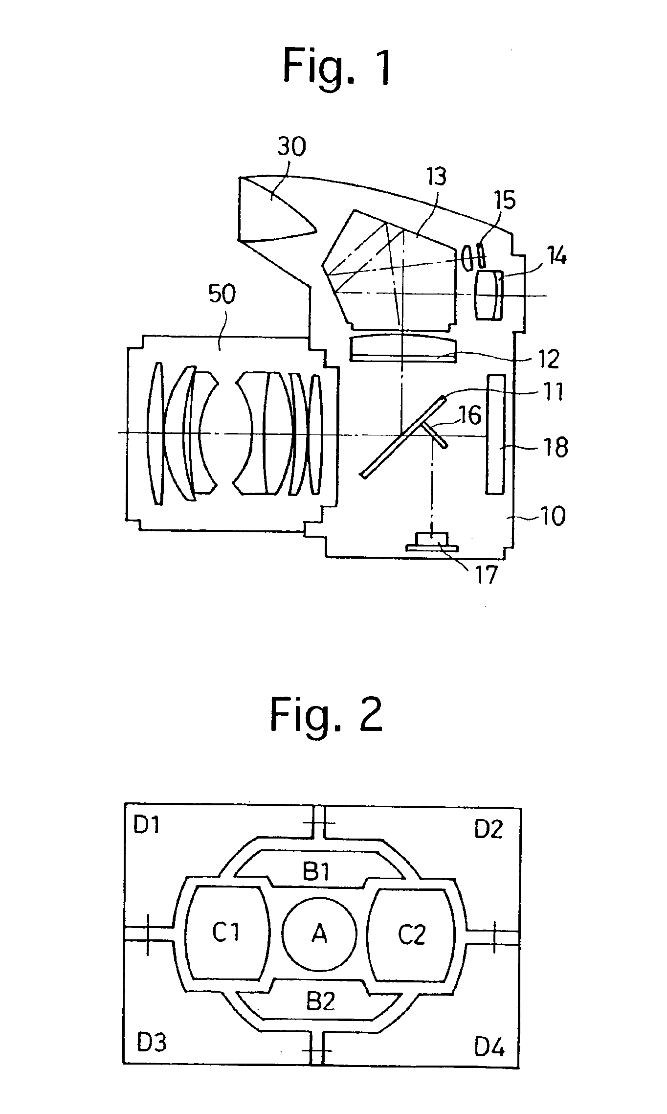
[0024]FIG. 1 shows an embodiment of an SLR digital camera to which the present invention is applied. This SLR digital camera is provided with a camera body 10 and a photographing lens 50 which is detachably attached to the camera body 10. The camera body 10 incorporates a built-in flash including a light emitting portion 30. The camera body 10 is provided with an image pick-up device 18 which is positioned in the camera body 10 on the image plane formed through the photographing lens 50. The image pick-up device 18 is a two-dimensional color image sensor such as a CCD image sensor or a CMOS (Complementary Metal-Oxide Semiconductor) image sensor.

[0025]As shown in FIG. 1, the camera body 10 is provided on an optical axis of the photographing lens 50 with a main mirror (quick-return mirror) 11, a sub-mirror 16 and the image pick-up device 18, in that order from the photographing lens 50. The main mirror 11 is provided at a center thereof with a half mirror portion so that the light pas...


PUM


Abstract

A light emission control system for a flash device includes a plurality of photometering sensors for photometric measurements on different photometering zones; and a controller which outputs a periodic pulsed trigger signal for activating the flash device, and sequentially selects analog signals output from the plurality of photometering sensors to convert the analog signals into digital signals in sequence. The controller outputs the pulsed trigger signal having a predetermined pulse frequency to perform a pre-flash emission operation in which the flash device is activated to discharge intermittently. The controller subsequently converts each analog signal into a corresponding digital signal in sequence in accordance with each trigger pulse of the periodic pulsed trigger signal before performing a main flash emission operation in which the flash device is activated to discharge at a time of exposure.

Description

BACKGROUND OF THE INVENTION[0001]1. Field of the Invention[0002]The present invention relates to a light emission control system for controlling light emissions of a flash device, wherein the control system is capable of emitting a preliminary flash emission before a main flash emission.[0003]2. Description of the Related Art[0004]Conventional cameras having a light emission control system for a flash device (electronic flash) in which the amount of light of the main flash discharge is controlled in accordance with photometric readings taken at a pre-flash emission stage (preliminary flash emission), which is emitted before the main flash discharge, are known in the art. However, in a camera in which “split” photometering is possible, it is difficult to photometer the entire photometering area by a single preliminary flash emission.[0005]A light emission control system for a flash device in which a stop timing of light emission of the flash device is controlled with no pre-flash emi...

Claims


Application Information

Patent Timeline
Patent Type & Authority Patents(United States)
IPC IPC(8): G03B7/08G03B7/28G03B7/16G03B15/03G03B15/05G03B15/02H05B41/30H05B41/32H04N5/235
CPCG03B7/16G03B15/05H04N5/2354G03B2215/0503G03B7/17H04N23/74
Inventor OKABE, HIROYUKI
Owner RICOH IMAGING COMPANY
Why Eureka
Try Eureka