Robot having offset rotary joints

a technology of rotary joints and robots, applied in the direction of electric programme control, system for re-entry to earth, program control, etc., can solve the problem that multi-functional robots have not been proposed, and achieve the effect of facilitating take-off and landing on uneven ground

Inactive Publication Date: 2005-07-26
JAPAN AEROSPACE EXPLORATION AGENCY
View PDF19 Cites 37 Cited by
  • Summary
  • Abstract
  • Description
  • Claims
  • Application Information

AI Technical Summary

Benefits of technology

[0005]An object of the present invention is to provide a robot leg structure whereby a robot may be obtained having the aforementioned functions that are demanded for planetary landing vehicles etc or extreme operations robots etc

Problems solved by technology

Since in many cases the shape condition of the surface is unknown when landing on the surface of the moon, Mars or other planets, it may be assumed that a planetary landing vehicle used to land on for exampl

Method used


Image

  • Robot having offset rotary joints
  • Robot having offset rotary joints
  • Robot having offset rotary joints

Examples


embodiment 1

[0031][Embodiment 1]

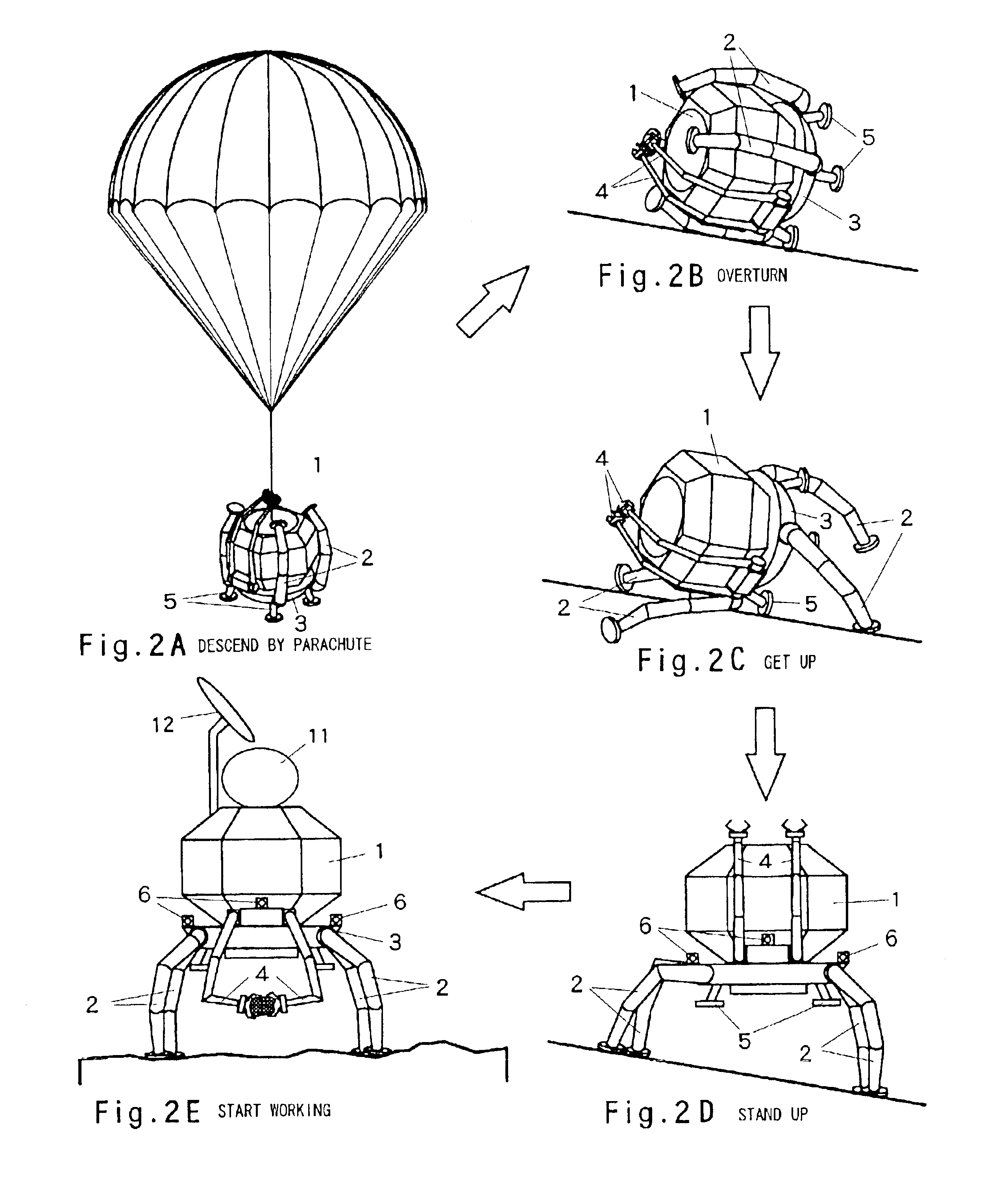
[0032]A first embodiment of a robot according to the present invention is shown in FIG. 2 and FIG. 3. The main robot body 1 consists of a polyhedron with a trunk of hexagonal pillar shape and whose top and bottom faces consist of hexagons which are smaller than the cross-section of the hexagonal pillar, and upper and lower inclined faces of hexagonal pyramidal shape joining the faces of the trunk and the top and bottom hexagonal faces, the top face being fitted with a parabolic antenna 12 and a space hatch 11 for accommodating collected samples and the lower face being fitted with the jet nozzle 13 of a rocket engine. The root of a multi-joint robot of a type having six arms is fixed to a base 3 for carrying and fixing the main robot body; of these six arms, four consist of legs 2 for performing a leg function and a pair of two arms constitute arms 4 for a hand function. The leading end ground-engaging member 20 for the leg function 2 is disk-shaped, suited for s...

embodiment 2

[0037][Embodiment 2]

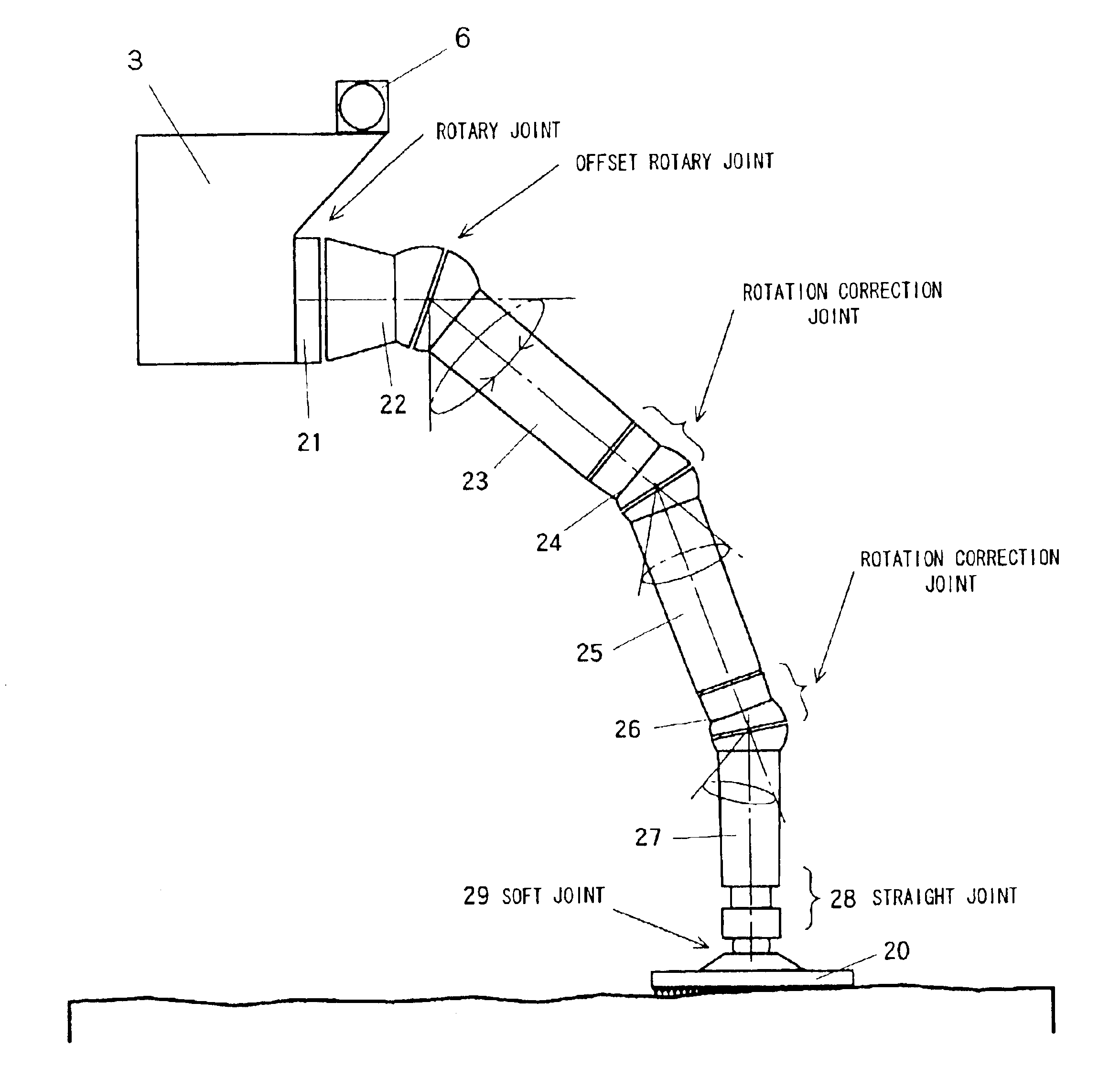
[0038]A second embodiment of the present invention is described with reference to FIG. 6 to FIG. 8. The aspect in which this embodiment differs from the preceding embodiment is the provision of a running mechanism in this embodiment. The main body 1 of the robot is unchanged. In FIG. 6, whereas 3 is a base where the main body 1 of the robot is placed and fixed and the root of the legs of an arm type multi-joint robot is fixed to this base 3, a simple rotary joint is constituted between the root 21, which is the fixing portion of this arm type multi-joint robot, and the initial arms 22 that are linked thereto and a simple offset joint is constituted between the initial arms 22 and the first arms 23 that are linked to the leading ends thereof. It is the same as the previous embodiment in that a rotation correction arm 24 is linked to this first arm 23 and a second arm 25 that is driven in rotation about an axis that obliuely intersects this rotation correction arm ...

third embodiment

[0040][Third embodiment]

[0041]Whereas the previous two embodiments envisioned chiefly a space robot, the presently illustrated embodiment is an embodiment of a robot envisioning terrestrial tasks. This is ideal as a robot for working in locations, albeit terrestrial, where there are geographically adverse conditions represented by deep holes or the bottom of valleys regions that it is difficult for human beings to enter such as for example deserts or deep forests, or for working in dangerous zones such as regions where toxic gases are generated or where there are radioactive substances. The construction in which four legs 2 for the leg function and a pair of arms 4 for the hand function, video cameras 6 and four short feet 5 are mounted on the base 3 is the same as in the case of the first embodiment. Since this is for terrestrial use, there is no need to provide a rocket engine in the main body and, instead, lowering or raising using a helicopter etc is envisioned; a strong wire su...


PUM


Abstract

A robot is obtained having various functions that are demanded for planetary landing vehicles, extreme operations robots or the like, in particular to provide a leg structure for a robot that is capable of getting up itself when overturned, facilitating take-off and landing on uneven ground, and that has a walking function and that has a hand function capable of three-dimensional operation. A robot comprises a main robot body and at least three legs mounted on this main body for enabling three-dimensional movement of the main robot body such as a self-erecting action or walking action; each leg is constituted by a multi-joint arm having a plurality of said offset rotary joints linked together and has a ground-engaging member mounted at the leading end of the arm, so that each leg is capable of independently controlled three-dimensional movement and drive.

Description

BACKGROUND OF THE INVENTION[0001]1. Field of the Invention[0002]The present invention relates to a leg mechanism for a robot and in particular relates to a leg mechanism for a planetary exploration robot or extreme operations robot comprising a plurality of legs that are capable of three-dimensional movement and are capable of being independently driven and controlled, which is capable of self-righting when overturned and which facilitates take-off and landing on uneven ground.[0003]2. Description of the Related Art[0004]Since in many cases the shape condition of the surface is unknown when landing on the surface of the moon, Mars or other planets, it may be assumed that a planetary landing vehicle used to land on for example the lunar surface and collect surface materials etc may be unable to maintain its normal posture and may overturn on landing. Also, when returning, it is considered to be necessary to support the return vehicle in the normal posture for purposes of the rocket j...

Claims


Application Information

Patent Timeline
IPC IPC(8): B25J17/02B25J9/06B62D57/00B64G1/16B62D57/028B64G1/00B64G1/62B64G1/22B25J5/00B25J13/08
CPCB25J9/06B25J17/025B62D57/028B64G1/16B64G1/62
Inventor OKAMOTO, OSAMUNAKAYA, TERUOMISUZUKI, SEIZOYAMAGUCHI, ISAOKAMIMURA, HEIHACHIROMATSUMOTO, KOTAROWAKABAYASHI, SACHIKOSASA, SHUICHI
Owner JAPAN AEROSPACE EXPLORATION AGENCY
Why Eureka
Try Eureka