Attachment for hair dryers

a hair dryer and attachment technology, which is applied in the field of hair dryers, can solve the problems of inability to achieve optimum drying of hair in a minimum period of time, inability to employ hair dryers, and inability to meet all consumer demands, so as to increase the volume of air, the effect of increasing or decreasing the amount of air capable of entering the hair dryer attachment of the present invention

Inactive Publication Date: 2005-08-02
ROVCAL +1
View PDF8 Cites 34 Cited by
  • Summary
  • Abstract
  • Description
  • Claims
  • Application Information

AI Technical Summary

Benefits of technology

[0014]By employing the present invention, all of the difficulties and drawbacks found in prior art hair dryers and hair dryer attachments have been overcome and a hair dryer attachment is realized which is capable of substantially reducing the drying time required for drying the hair of any individual, while also being easily employed and comfortable. In accordance with the present invention, two unique construction elements are provided in a single hair dryer attachment which is merely affixed to the exit portal of any conventional hair dryer to achieve the substantially improved and enhanced results.
[0015]In the present invention, a hair dryer attachment is attained which incorporates a substantially circular entry zone or portal constructed for being quickly and easily affixed to any conventional circular shaped hair dryer exit portal. In addition, the opposed or exit end of the hair dryer attachment of the present invention is formed incorporating an enlarged, diverging wall configuration, constructed for channeling and directing the air flowing through the hair dryer attachment to expand or fan outwardly as the air flow exits the attachment. In this way, the air flow stream exiting in the attachment is maximized.
[0016]In addition, cooperating with the enlarged, expanding, exit portal of the attachment of the present invention, the present invention also incorporates a plurality of inlet portals formed on the outer surface of the attachment, directly adjacent to the circular shaped entry zone. In the preferred embodiment, at least one raised, sloping panel is formed adjacent the inlet portal of the attachment with the panel sloping outwardly from the generally circular shaped inlet portal. In addition, a plurality of apertures or portals are formed in the panel for enabling ambient air to freely flow therethrough.

Problems solved by technology

However, in spite of the substantial effort that has been expended in developing a universally acceptable hair dryer, the industry has failed to achieve a hand-held hair dryer which is capable of satisfying all of the consumer demands imposed thereon.
In this regard, one principal objection raised by many users is the inability of achieving optimum drying of one's hair in a minimum period of time.
However, although increased temperatures have been realized, consumers have been reluctant to employ hair dryers having substantially increased air flow temperatures, due to the discomfort produced by these products.
Although some of these attachments have met with some success in satisfying consumer needs, these products have been incapable of achieving universal acceptance by all consumers.
In general, these prior art attachments tend to be large and / or extremely bulky in size, causing the user to experience added weight during the hair drying process, as well as causing the hair dryer itself to have an altered center of gravity.
As a result, the user experiences substantial difficulty and inconvenience in holding and supporting the hair dryer, due to the added weight and bulk of the attachment affixed to the discharge end of the hair dryer.
Due to these difficulties and inconveniences, these prior art products have not been widely accepted.

Method used


Image

  • Attachment for hair dryers
  • Attachment for hair dryers
  • Attachment for hair dryers

Examples


Embodiment Construction

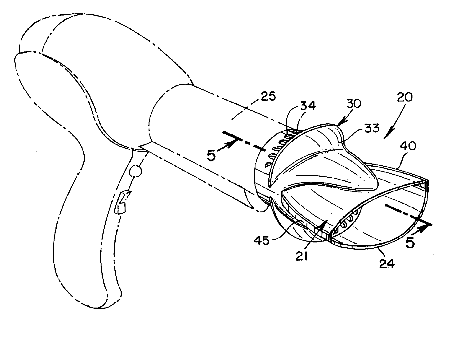
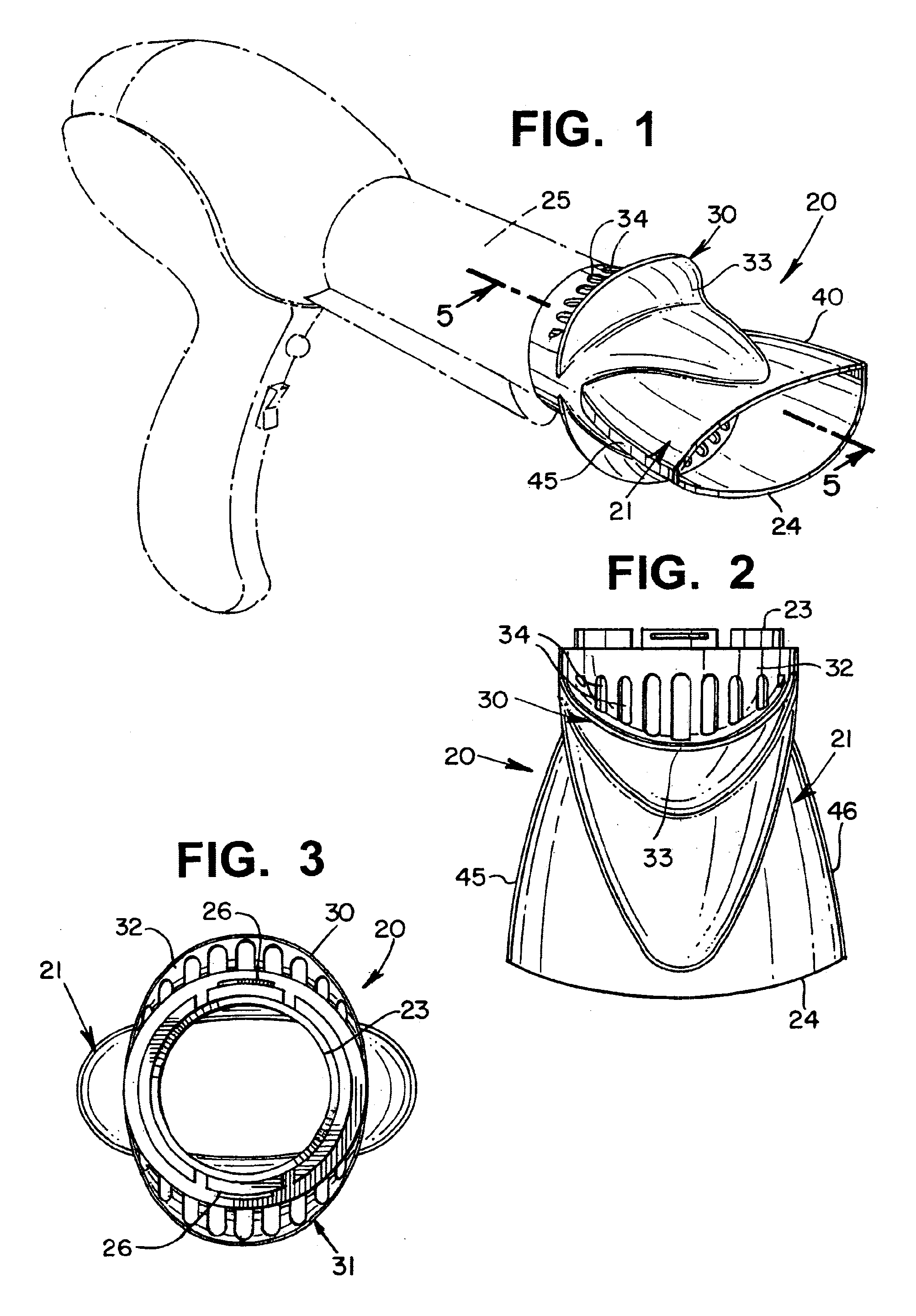
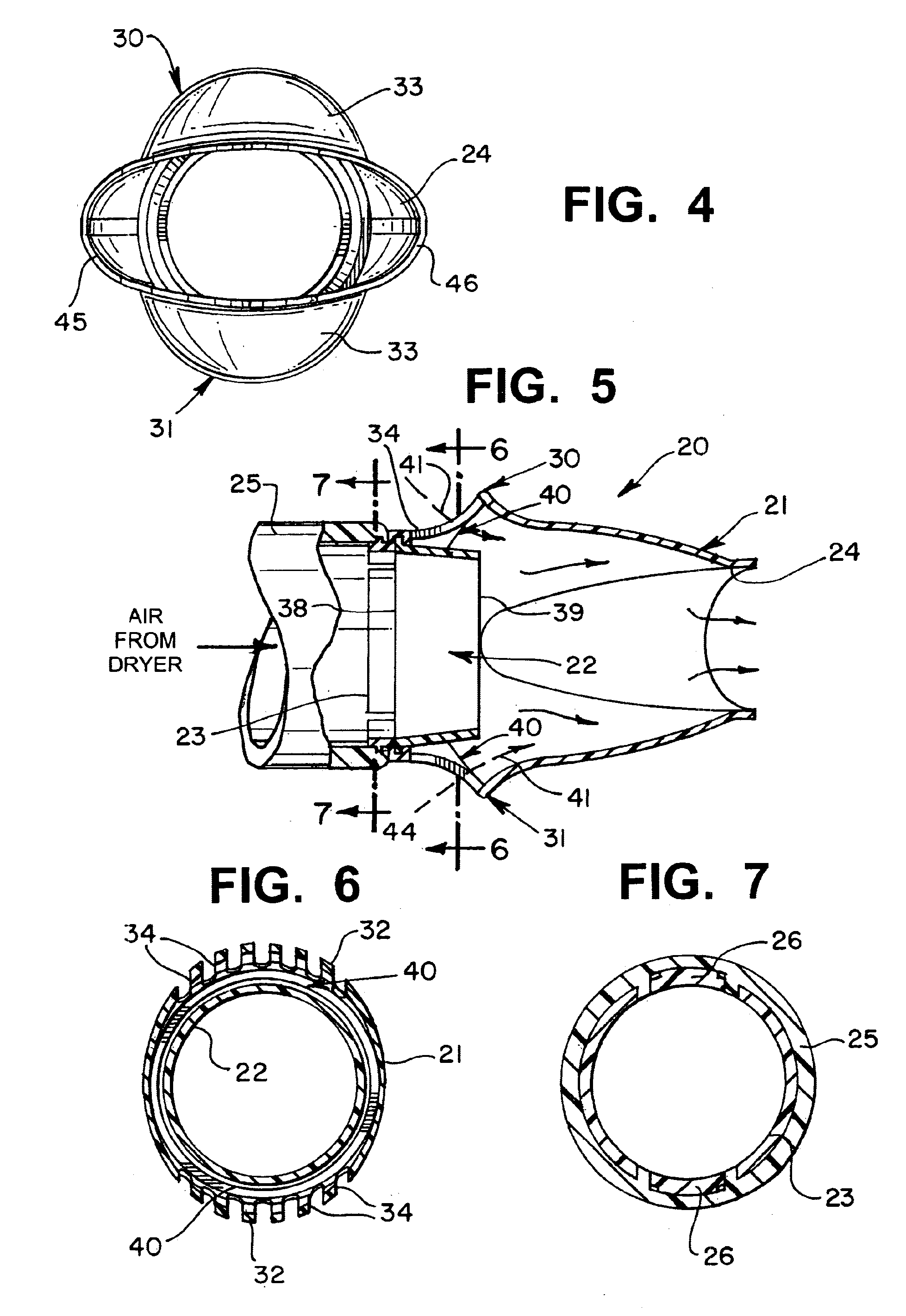
[0036]By referring to FIGS. 1-10, along with the following detailed discussion, the construction and operation of the two preferred, alternate embodiments of the hair dryer attachment of the present invention can best be understood. Although the preferred embodiments of the present invention are fully disclosed herein, further alternate constructions may be implemented without departing from the scope of this invention. Consequently, it is to be understood that this detailed disclosure is provided for exemplary purposes only and is not intended as a limitation of the present invention.

[0037]As fully depicted in FIGS. 1-10, hair dryer attachment 20 of the present invention comprises a uniquely constructed housing 21 in combination with inner tube member 22. In addition, outer housing 21 incorporates a circular shaped inlet portal 23 and an outlet portal 24.

[0038]In the preferred embodiments, inlet portal 23 is constructed for being quickly and easily securely mounted to the exit port...


PUM


Abstract

By providing a plurality of portals in a housing which forms a hair dryer attachment which is merely fixed to the exist portal of any conventional hair dryer, a hair dryer attachment is realized which is capable of substantially reducing the drying time required for drying the hair of any individual, while also being easily employed and comfortable. In the preferred embodiment, at least one raised, sloping panel is formed adjacent the inlet portal of the attachment with the panel sloping outwardly from the generally circular shaped inlet portal. In addition, a plurality of apertures or portals are formed in the panel for enabling ambient air to freely flow therethrough. In this way, the heated air flowing through the central portion of the attachment creates a low-pressure zone on the inside surface of the portals, drawing ambient air through the portals into the interior of the hair dryer attachment, thereby enabling the quantity of the air reaching the hair of the user is substantially increased.

Description

RELATED APPLICATIONS[0001]This application is related to U.S. Provisional Application Ser. No. 60 / 438,542, filed Jan. 6, 2003, entitled ATTACHMENT FOR HAIR DRYERS.TECHNICAL FIELD[0002]This invention relates to hair dryers and, more particularly, to an attachment for a hair dryer which substantially enhances and improves the drying of the hair fibers.BACKGROUND ART[0003]Men and women have had, for many decades, the desire of drying their hair after washing. Typically, a hand-held hair dryer is employed, which is constructed for drawing ambient air through an elongated passageway in which a heat source is retained. As the air flows over the heat source, the temperature of the following air is raised, with the heated air being channeled to an exit portal where the heated air is applied to the user's wet hair fibers. By continuously exposing the wet hair fibers to the heated air stream, the desired drying effect is realized.[0004]In order to meet the substantial demand that has been dev...

Claims


Application Information

Patent Timeline
Patent Type & Authority Patents(United States)
IPC IPC(8): A45D20/00A45D20/12
CPCA45D20/122
Inventor ANDREW, MICHAEL A.MICINILIO, GREGG A.TOBIN, RICHARD NEILWILCOX, JOHN
Owner ROVCAL
Why Eureka
Try Eureka