Plow cutting edge

a cutting edge and blade technology, applied in the field of plowing blades, can solve the problems of generating undesirable costs, causing significant cost, and ordinary wear from scraping against the roadway, and achieve the effect of not binding or rapidly wear

Active Publication Date: 2005-08-02
BURKE TRUCK & EQUIP
View PDF46 Cites 37 Cited by
  • Summary
  • Abstract
  • Description
  • Claims
  • Application Information

AI Technical Summary

Benefits of technology

[0008]A plow moldboard cutting edge includes a cutting edge blade having a front (leading) face and a rear (trailing) face, with one or more receiving apertures defined therebetween. An elastic bushing is then provided in each of the receiving apertures of the cutting edge blade, with each bushing having a through hole defined therein. The cutting edge blade is then fastened to the lower edge of a plow moldboard by extending fasteners through cutting edge mounting holes defined in the plow moldboard adjacent its lower edge, and then into the through holes of the bushings. The fasteners secure the bushings to the plow moldboard, and thereby mount the cutting edge blade (which is situated about the elastic bushings) to the plow moldboard as well, with the elastic bushings elastically spacing the cutting edge blade from the fasteners. As a result, when the cutting edge blade is driven along a roadway or other surface to be plowed, the elastic bushings elastically suspend the cutting edge blade from the moldboard so that the cutting edge blade rides along the plowing surface and better conforms to the plowing surface's contour. The elastic bushings additionally help to avoid shock transmission between the cutting edge blade and moldboard, and assist in reducing wear on the cutting edge blade.
[0010]The elastic bushings preferably include nonelastic (e.g., metal) bushings lining their through holes, so that the through holes of the nonelastic bushings effectively define the through holes of the elastic bushings. The lengths of the nonelastic bushings (as measured along the axes of their through holes) are preferably greater than the thicknesses of the elastic bushings (as measured in the same dimension) so that the nonelastic bushings help hold the moldboard and any mounting member in spaced relationship, and maintain some small amount of space between these components and the elastic bushings. The elastic bushings may therefore elastically displace during plowing operations without being held against the moldboard (and / or any mounting member), so that they do not bind or rapidly wear.

Problems solved by technology

However, these “trip” cutting edge arrangements merely protect against impact damage; ordinary wear from scraping against the roadway is not relieved.
Apart from generating undesirable costs from the standpoint of the material cost of blade replacement, the need to replace a worn cutting edge also generates significant costs in terms of lost usage of plowing vehicles, and time lost by plowing personnel to maintenance rather than to plowing operations.
In the snowplowing field, where the economic cost of unplowed roads (and the resulting delays in transportation and commerce) can be very significant, lost time is a critical concern.
While these often allow a cutting edge to last longer, they may nevertheless exacerbate disadvantages in replacement costs and maintenance time.
However, a significant disadvantage of the JOMA cutting edge is its cost: the expense of generating the multi-part segments or “shares,” and embedding them within an elastomer mount, is significantly greater than the cost of a standard one-piece, all metal cutting edge.

Method used


Image

  • Plow cutting edge
  • Plow cutting edge

Examples


Embodiment Construction

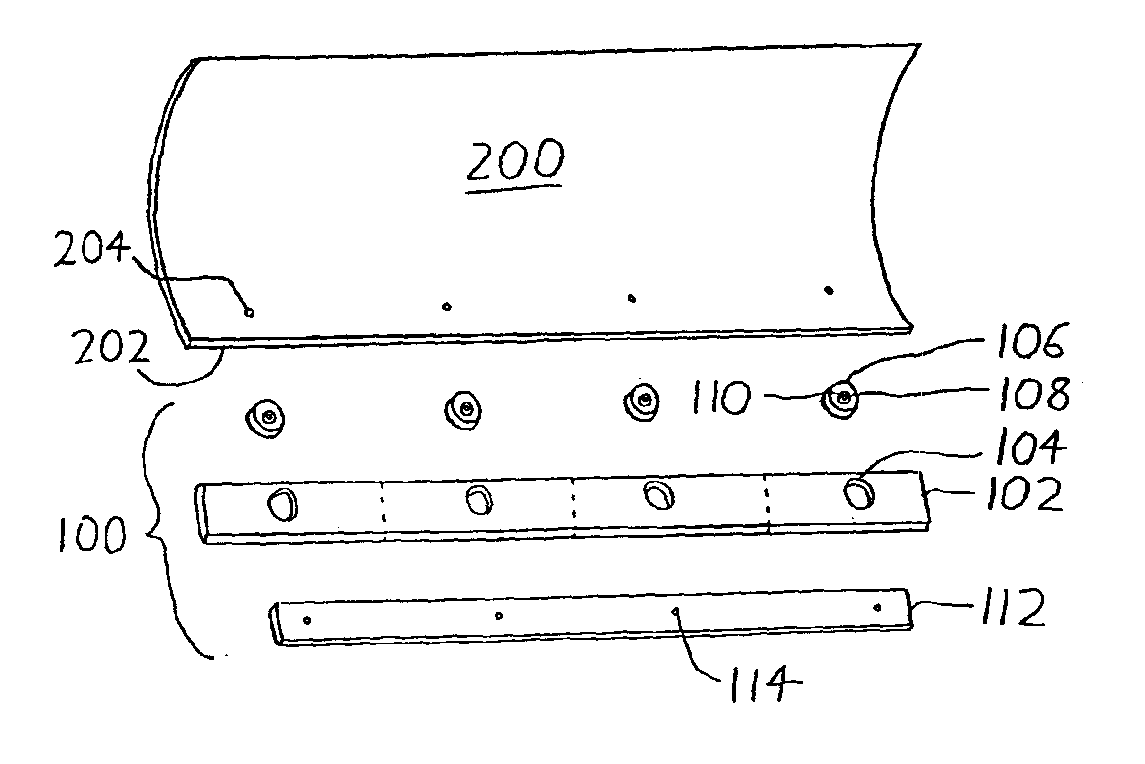
[0014]A preferred version of the invention is depicted in the accompanying drawings. Referring initially to the exploded assembly view of FIG. 1, a moldboard 200 has a lower edge 202 along which are spaced a number of cutting edge mounting holes 204. A cutting edge 100 then includes:

[0015](1) A cutting edge blade 102, which is generally similar to a standard cutting edge save that it has a number of receiving apertures 104 defined along its length, each receiving aperture 104 being generally coaxial with one of the cutting edge mounting holes 204 on the lower edge 202 of the moldboard 200;

[0016](2) A number of elastic bushings 106, each of which has an outer diameter sized to be closely received within one of the receiving apertures 104, and an inner diameter lined with a metal bushing 108 with a through hole 110 sized similarly to a cutting edge mounting hole 204; and

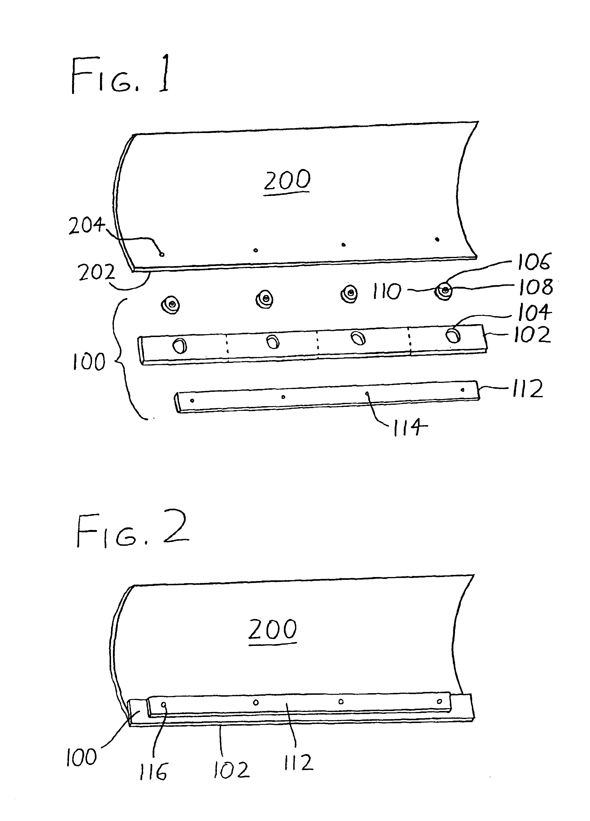
[0017](3) A mounting member 112, shown in FIGS. 1 and 2 in the exemplary form of a plate, which has a number of moun...


PUM


Abstract

A plow moldboard cutting edge includes a cutting edge blade having a front (leading) face and a rear (trailing) face, with one or more receiving apertures defined therebetween. An elastic bushing is then provided in each of the receiving apertures of the cutting edge blade, with each bushing having a through hole defined therein. The cutting edge blade is then fastened to the lower edge of a plow moldboard by extending fasteners through cutting edge mounting holes defined in the plow moldboard adjacent its lower edge, and then into the through holes of the bushings. The fasteners secure the bushings to the plow moldboard, and thereby mount the cutting edge blade (which is situated about the elastic bushings) to the plow moldboard as well, with the elastic bushings elastically spacing the cutting edge blade from the fasteners. As a result, when the cutting edge blade is driven along a roadway or other surface to be plowed, the elastic bushings elastically suspend the cutting edge blade from the moldboard so that the cutting edge blade rides along the plowing surface and better conforms to the plowing surface's contour. The elastic bushings additionally help to avoid shock transmission between the cutting edge blade and moldboard, and assist in reducing wear on the cutting edge blade.

Description

CROSS-REFERENCE TO RELATED APPLICATIONS[0001]This application claims priority under 35 USC §119(e) to U.S. Provisional Patent Application 60 / 453,619 filed 11 Mar. 2003, the entirety of which is incorporated by reference herein.FIELD OF THE INVENTION[0002]This document concerns an invention relating generally to plowing blades, and more specifically to the cutting edge of a plowing blade (at which the blade rides along the surface being plowed).BACKGROUND OF THE INVENTION[0003]Plowing action in a snowplow (or other type of plow) is generally effected by the plowing vehicle's moldboard, the (usually curved) shovel-like blade situated in front of the plowing vehicle. At the lower edge of the moldboard, a sacrificial cutting edge is usually provided—a strip of hardened steel, generally carbide steel, which is bolted to the bottom of the moldboard and which is intended to bear the brunt of the wear (rather than the moldboard itself) as the cutting edge scrapes along the roadway. Exemplar...

Claims


Application Information

Patent Timeline
Patent Type & Authority Patents(United States)
IPC IPC(8): E02F3/76E02F3/815
CPCE02F3/8152
Inventor JONES, JAYSON D.SMITH, JEFF J.
Owner BURKE TRUCK & EQUIP
Why Eureka
Try Eureka