Modified flat wall modular insulated concrete form system

a modular, concrete technology, applied in the direction of walls, buildings, building roofs, etc., can solve the problems of inconvenient calculation of form components, difficulty in properly positioning fastener positions for attaching building elements, and inability to accurately calculate the amount of concrete consumed, so as to maximize the insulation value of the wall and maximize the strength of the wall

Inactive Publication Date: 2005-08-02
SCHMIDT DONALD L
View PDF7 Cites 10 Cited by
  • Summary
  • Abstract
  • Description
  • Claims
  • Application Information

AI Technical Summary

Benefits of technology

[0016]Preferably, the posts and beams are configured as parallelepipeds so that all constituent material thereof contributes to compressive strength in at least one direction of an orthogonal or Cartesian system. No concrete is thus ineffectually used. Overall building costs and weight are minimized, while still affording maximal strength. Also, volume within the form devoted to insulating material is maximized, thereby maximizing temperature insulating value of the form.
[0026]It is an object of the invention to provide improved elements and arrangements thereof in an apparatus for the purposes described which is inexpensive, dependable and fully effective in accomplishing its intended purposes.

Problems solved by technology

A second problem of prior art forms is that they are not designed such that locations of tie brackets coincide with the ends of standard building elements.
This arrangement will likely interfere with even spacing apart of tie brackets at even distance intervals of a whole number of feet since the two abutting end brackets will be spaced on either side of the center line.
This makes it difficult to properly locate fastener positions for attaching building elements to the form.
Flange location can be calculated, but calculation entails additional effort when constructing forms.
Another problem is that the prior art has not provided insulating concrete form walls which are conducive to laying a wall in increments of one foot, as measured from the outside corner, as is frequent construction practice.
Another problem of existing waffle grid insulating concrete forms is that none known to the present inventor has means for interlocking with forms of courses above and below.

Method used


Image

  • Modified flat wall modular insulated concrete form system
  • Modified flat wall modular insulated concrete form system
  • Modified flat wall modular insulated concrete form system

Examples


Embodiment Construction

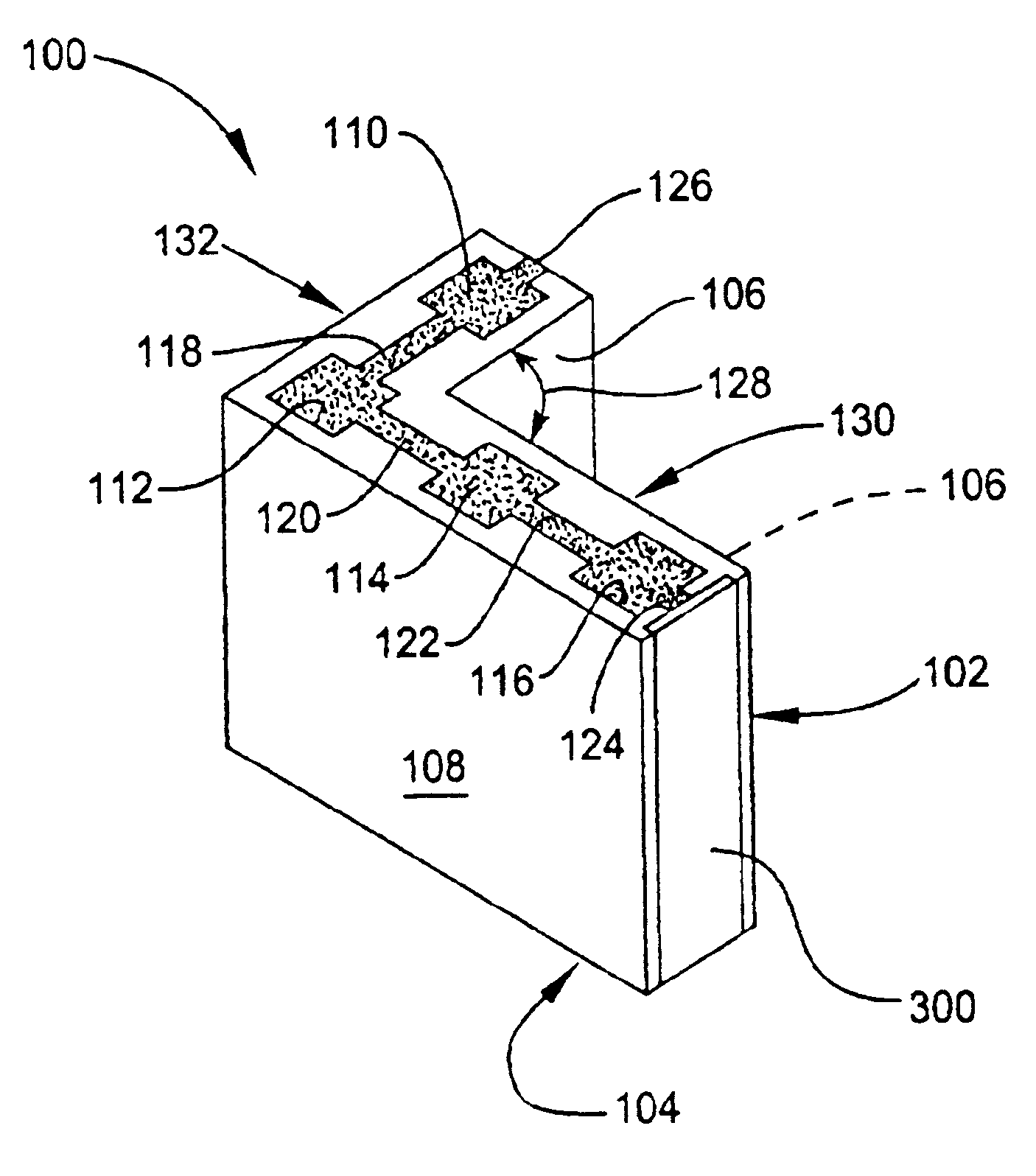
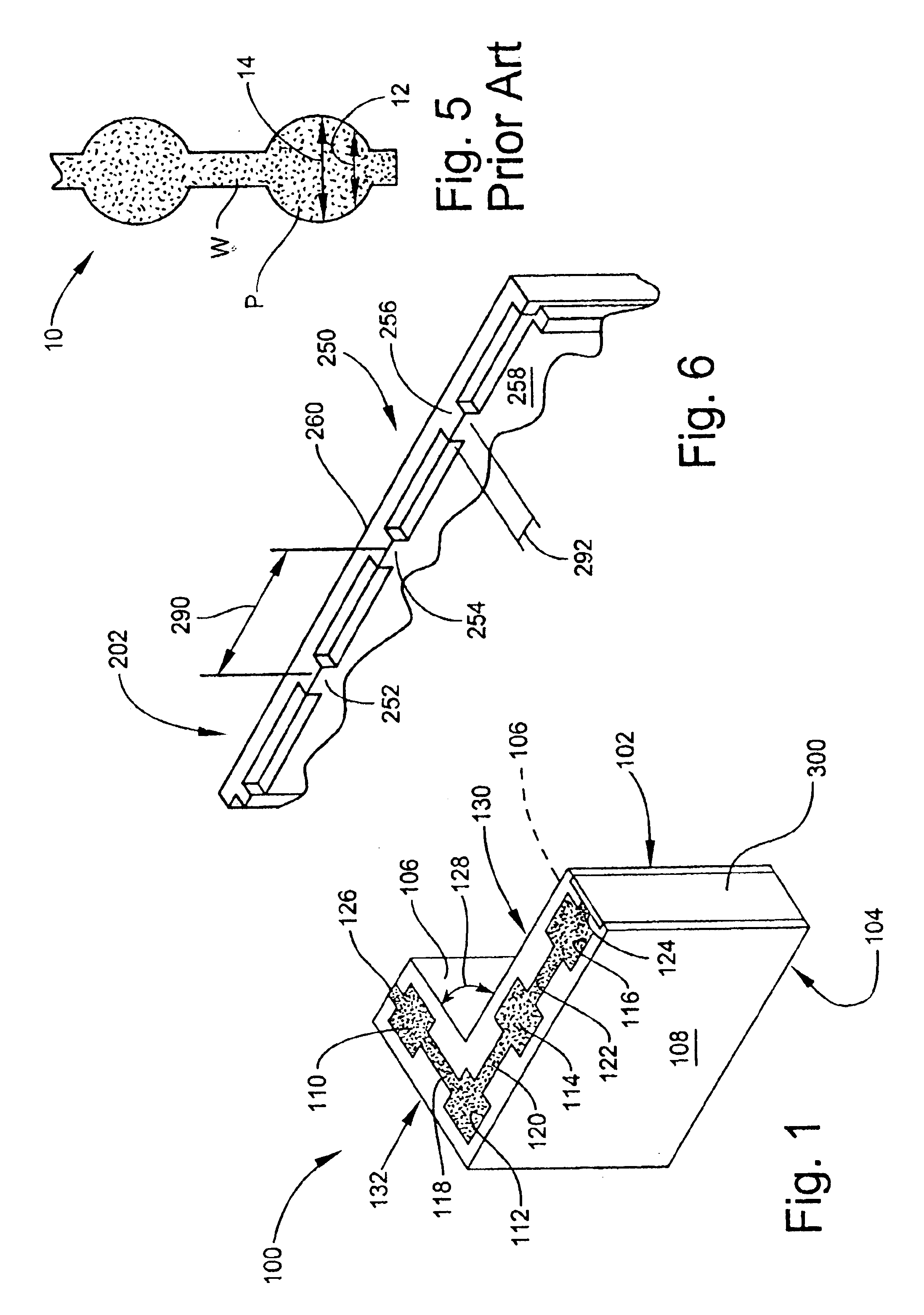
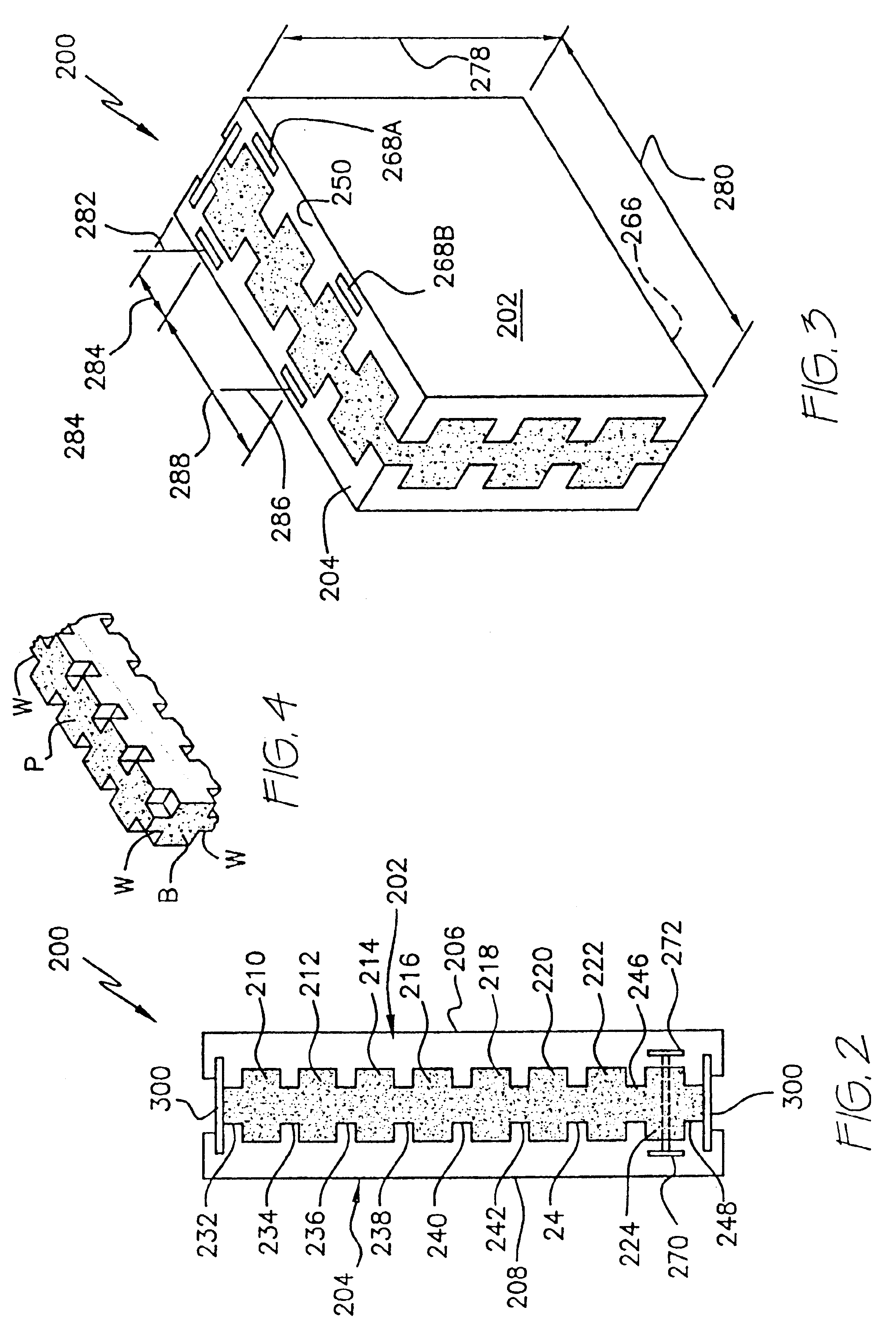
[0039]The present invention provides improved insulating concrete forms for receiving poured concrete to form an insulated structural wall of a building (not shown). A corner form 100 is depicted in FIG. 1. A preferred configuration is more particularly set forth in my co-pending patent application Ser. No. 09 / 932,096, filed on Aug. 20, 2001. A corresponding straight form 200 is shown in FIG. 2. Buildings having conventional rectangular floor plan features may be constructed employing both forms 100, 200. Referring to FIGS. 1 and 2, insulating concrete form 100 includes a first insulating panel 102 and a second insulating panel 104. Panels 102, 104 are preferably formed from expanded polystyrene or other synthetic resin closed cell foam. Each panel 102 or 104 has an interior surface concealed from view in FIG. 1, wherein form 100 is shown filled with concrete (indicated by stippling) for clarity of the view. Each panel 102 or 104 has a flat exterior surface (106 or 108, respectively...


PUM


Abstract

Improved, modified flat wall insulating concrete forms similar to a “waffle grid” type for generating posts, beams, and interconnecting webs of concrete. The novel forms incorporate interlocking structure for a plural vertically stacked forms. The forms are provided as angled corner or straight forms having an overall length of four feet. Tie brackets connecting interior and exterior synthetic expanded foam walls of the form have flanges which are embedded within and concealed by the walls. Tie brackets are spaced apart from one another at one foot intervals, and from ends of the interior and exterior walls of the form by distance intervals of six inches. Interior and exterior walls are configured to enclose a void space therebetween. When filled with concrete, the space forms posts, beams, and webs filling openings which would otherwise occur among the posts and beams. The posts and beams, and webs are square or rectangular in cross section, presenting a uniform exterior panel thickness.

Description

[0001]This application is related to application Ser. No. 09 / 932,095 entitled CORNER FORM FOR A MODULAR INSULATING CONCRETE FORM SYSTEM and Ser. No. 09 / 932,096 entitled FORM BRACING TIE BRACKET FOR MODULAR INSULATING CONCRETE FORM SYSTEM AND FORM USING THE SAME, filed concurrently herewith on Aug. 20, 2000.BACKGROUND OF THE INVENTION[0002]1. Field of the Invention[0003]The present invention relates to modular insulating concrete forms of the type which receive poured concrete and are abandoned in place after pouring, thereby becoming an integral part of a static structure being built. The invention is particularly applicable to residential and light commercial construction. The novel forms are usable by homeowners, contractors, municipal, industrial, and institutional personnel in building and improving existing structures wherever insulated load bearing walls are to be built from poured concrete.[0004]2. Description of the Prior Art[0005]Left-in-place insulting concrete forms for b...

Claims


Application Information

Patent Timeline
Patent Type & Authority Patents(United States)
IPC IPC(8): E04B2/86
CPCE04B2/8617E04B2002/867E04B2002/8676
Inventor SCHMIDT, DONALD L.
Owner SCHMIDT DONALD L
Why Eureka
Try Eureka