Fuel supply apparatus

a technology of fuel supply and apparatus, which is applied in the direction of liquid fuel feeders, machines/engines, and feed systems, etc., can solve the problems of low degree of freedom of spring design such as spring constant, inferior dimension accuracy of fuel tanks, and easy deformation of fuel pumps, etc., to achieve simple construction

Inactive Publication Date: 2005-08-02
MITSUBISHI ELECTRIC CORP
View PDF10 Cites 44 Cited by
  • Summary
  • Abstract
  • Description
  • Claims
  • Application Information

AI Technical Summary

Benefits of technology

[0014]The invention has been made to solve the above-described problems, and provides a fuel supply apparatus which is capable of realizing stable fuel supply by following the positional variations of the bottom side of a fuel tank by means of a simple and inexpensive construction, and which is improved in ease of assembly in the fuel tank.
[0016]According to the invention, when the tank bottom travels toward or away from the tank opening, the sliding tube portion travels to follow the tank bottom while sliding on the guide tube portion owing to the urging force generated on the basis of the pressure of the fuel inside the fuel pump body. Accordingly, it is possible to obtain a fuel supply apparatus which is capable of following the positional variations of the bottom side of the fuel tank by mean of a simple construction and which is improved in terms of ease of assembly in the fuel tank.

Problems solved by technology

The fuel supply apparatus of Patent Document 1 is placed in abutment with the bottom side of the fuel tank, but if the fuel tank is formed of, for example, a molded resin product, the fuel tank is inferior in dimension accuracy and is easily deformed by the influence of the fuel temperature inside the fuel tank.
This leads to the problem that since the position of the bottom side of the fuel tank easily varies so that the liquid level of the fuel easily varies, it is difficult to ensure stable operation of the fuel pump.
It is to be noted that the fuel supply apparatus is formed to expand and shorten by means of the urging force of an elastic member such as a coiled spring, but in the case where the amount of deformation of the fuel tank is large, the degree of freedom of spring design such as spring constant becomes low in that such deformation cannot be easily absorbed by only the elastic member such as a coiled spring, so that the accuracy of the elastic member to follow the deformation is limited.
This construction entails a complicated structure and an increase in manufacturing cost due to an increase in the number of component parts.
Furthermore, the setting of the elastic modulus of the coiled spring needs to be made variously different for different uses, and in addition, the fatigue of the spring itself must be taken into account.
Accordingly, it is extremely difficult to design a fuel supply apparatus which can stand up to long hours of practical use.
In addition, the fuel supply apparatus of Patent Document 1 has the problem of being inferior in ease of assembly in the fuel tank.
Accordingly, the fuel supply apparatus of Patent Document 1 is complicated in assembly and inferior in operability.

Method used


Image

  • Fuel supply apparatus
  • Fuel supply apparatus
  • Fuel supply apparatus

Examples


embodiment 1

[0031

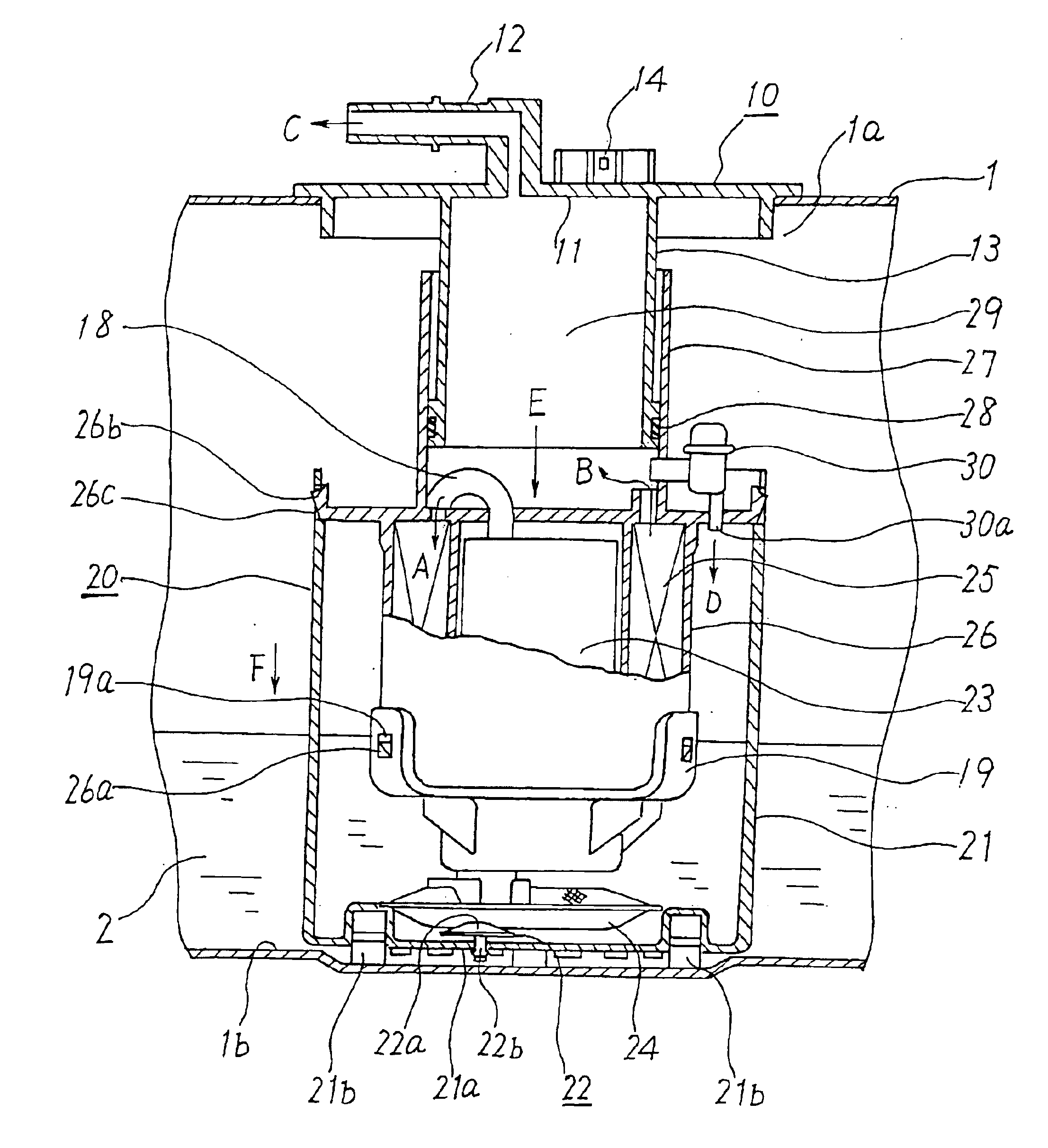
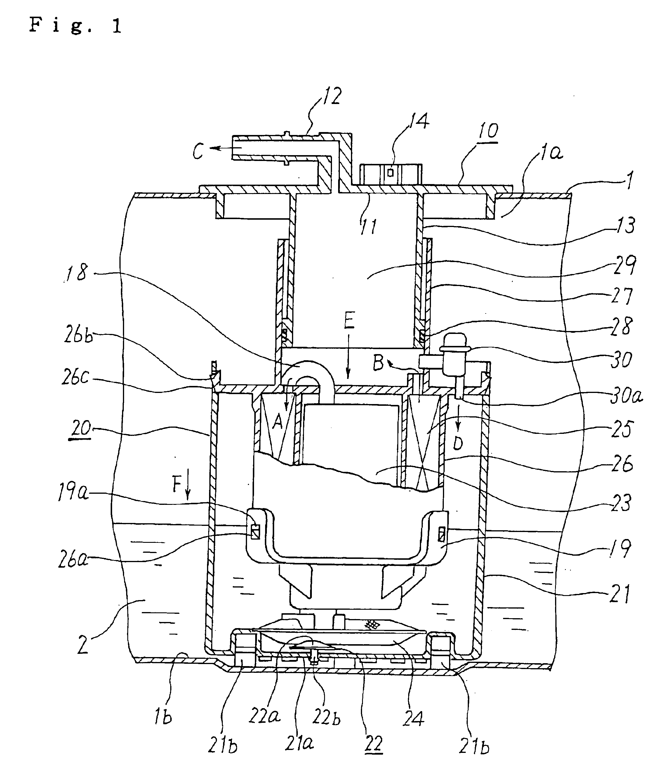
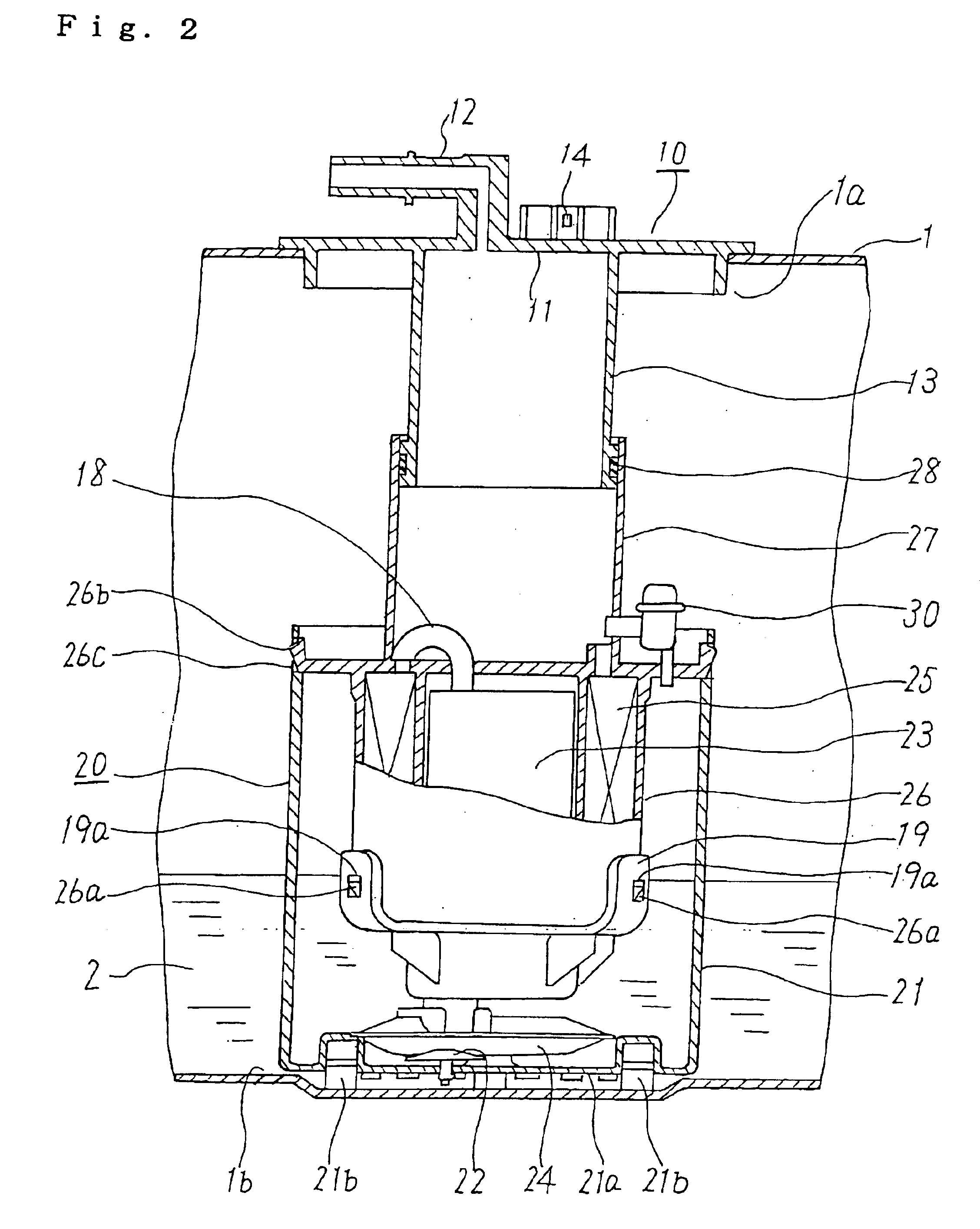
[0032]FIG. 1 is a longitudinal cross-sectional view of a fuel supply apparatus according to Embodiment 1 of the invention, and shows the case where the position of the bottom side of a fuel tank is shallow, while FIG. 2 is a longitudinal cross-sectional view of the fuel supply apparatus according to Embodiment 1 of the invention, and shows the case where the position of the bottom side of the fuel tank is deep. FIG. 3 is a bottom view of the fuel supply apparatus shown in FIG. 1, FIG. 4 is an enlarged view of the essential portion of FIG. 3, and FIG. 5 is an enlarged view of an air-tight member shown in FIG. 1.

[0033]Referring to FIG. 1, the fuel supply apparatus includes a fuel tank lid unit 10 which is externally fitted in a tank opening 1a formed in a fuel tank 1, and a fuel pump body 20 which is disposed in the fuel tank 1 so that the bottom side of the fuel pump body 20 can come into abutment with a tank bottom 1b and which stably discharges and supplies fuel 2 from the fue...

embodiment 2

[0050

[0051]FIG. 6 is a longitudinal cross-sectional view of a fuel supply apparatus according to Embodiment 2 of the invention, and shows the case where the position of the bottom side of the fuel tank is shallow, while FIG. 7 is a longitudinal cross-sectional view of the fuel supply apparatus according to Embodiment 2 of the invention, and shows the case where the position of the bottom side of the fuel tank is deep. In FIGS. 6 and 7, the same constituent elements and portions as those used in Embodiment 1 are denoted by the same reference numerals. The following description focuses on points different from Embodiment 1. The discharge port of the fuel filter 25 and the fuel discharge passage portion 12 are arranged to directly communicate with each other by means of a connecting member 31 which is formed in a coiled shape, whereby after the fuel discharged from the fuel filter 25 has flown into the connecting member 31 (in the direction of an arrow H), the fuel is transferred from ...

embodiment 3

[0054

[0055]A fuel supply apparatus according to Embodiment 3 is a modification of Embodiment 2, and FIG. 8 is a longitudinal cross-sectional view of the fuel supply apparatus, and shows the case where the position of the bottom side of the fuel tank is shallow, while FIG. 9 is a longitudinal cross-sectional view of the fuel supply apparatus, and shows the case where the position of the bottom side of the fuel tank is deep. In FIGS. 8 and 9, the same constituent elements and portions as those used in Embodiment 2 are denoted by the same reference numerals. The following description focuses on points different from Embodiment 2. The tank bottom 1b of the fuel tank 1 is formed to have a cavity portion 1c, and the bottom of the fuel pump body 20 is fitted in the cavity portion 1c so that the cavity portion 1c serves as a guide portion for guiding the vertical movement of the fuel pump body 20. In this construction, the guide tube portion 13 and the sliding tube portion 27 are omitted. I...


PUM


Abstract

A fuel supply apparatus capable of following the positional variations of the bottom side of a fuel tank through a simple construction and improved in terms of ease of assembly in the fuel tank. The apparatus includes a fuel pump body in which a filter-integrated pump in which a fuel pump and a fuel filter are integrally formed is integrally accommodated in a fuel reservoir having a bottom capable of coming into abutment with a bottom side of the fuel tank, and causes the fuel pump body to travel to follow the variations of the bottom side of the fuel tank so as to be placed in abutment with the bottom side of the fuel tank, by means of an urging force generated on the basis of the pressure of the fuel inside the fuel pump body.

Description

BACKGROUND OF THE INVENTION[0001]1. Field of the Invention[0002]The present invention relates to a fuel supply apparatus which is mounted in a fuel tank and is operative to stably supply fuel to an internal combustion engine, and more particularly, to a fuel supply apparatus of the type in which a fuel pump body is disposed in abutment with the bottom side of the fuel tank.[0003]2. Description of the Related Art[0004]In the field of fuel tanks used for supplying fuel to internal combustion engines such as automotive engines, a fuel supply apparatus has heretofore been known which is constructed to ensure stable operation of a fuel pump even when the liquid level in the fuel pump varies, by making use of a subtank in which the fuel pump is accommodated.[0005]For example, a fuel supply apparatus of the type in which a fuel pump body is mounted on the bottom side of a fuel tank is disclosed in JP-A-11-294282 (Patent Document 1, FIG. 3).[0006]FIG. 12 schematically shows the fuel supply ...

Claims


Application Information

Patent Timeline
Patent Type & Authority Patents(United States)
IPC IPC(8): F02M37/10F02M37/08F02M37/22F02M37/02F02M37/00
CPCF02M37/103F02M37/22F02M37/025F02M37/106F02M2037/225F02M2037/228F02M37/44F02M37/46F02M37/48F02M37/50
Inventor MITSUDOU, HIDEOHIRAIWA, MASARUHAYASHI, MICHIHIROINOUE, SEIZO
Owner MITSUBISHI ELECTRIC CORP
Why Eureka
Try Eureka