Gripper housing
a technology for grippers and housings, applied in the field of gripper housings, can solve the problem of limit to such a reduction in siz
- Summary
- Abstract
- Description
- Claims
- Application Information
AI Technical Summary
Benefits of technology
Problems solved by technology
Method used
Image
Examples
Embodiment Construction
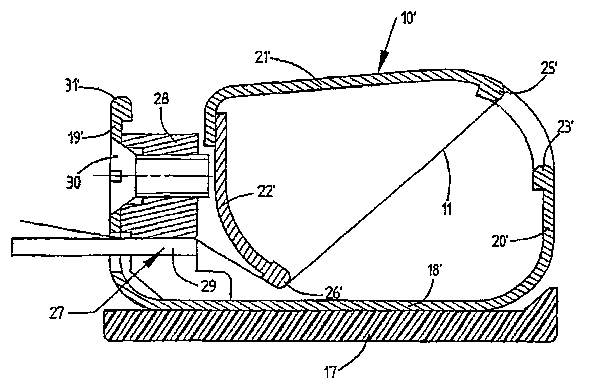
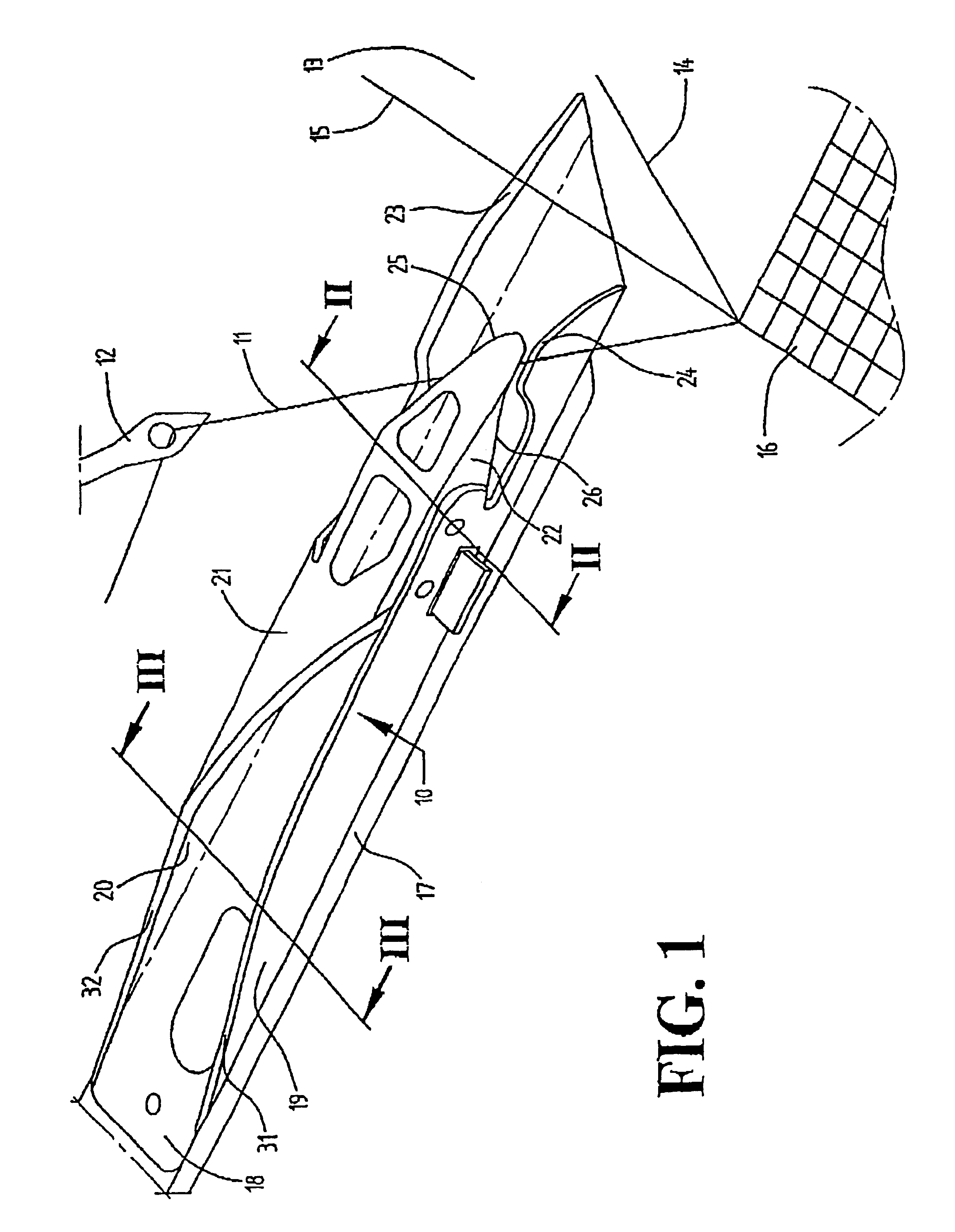
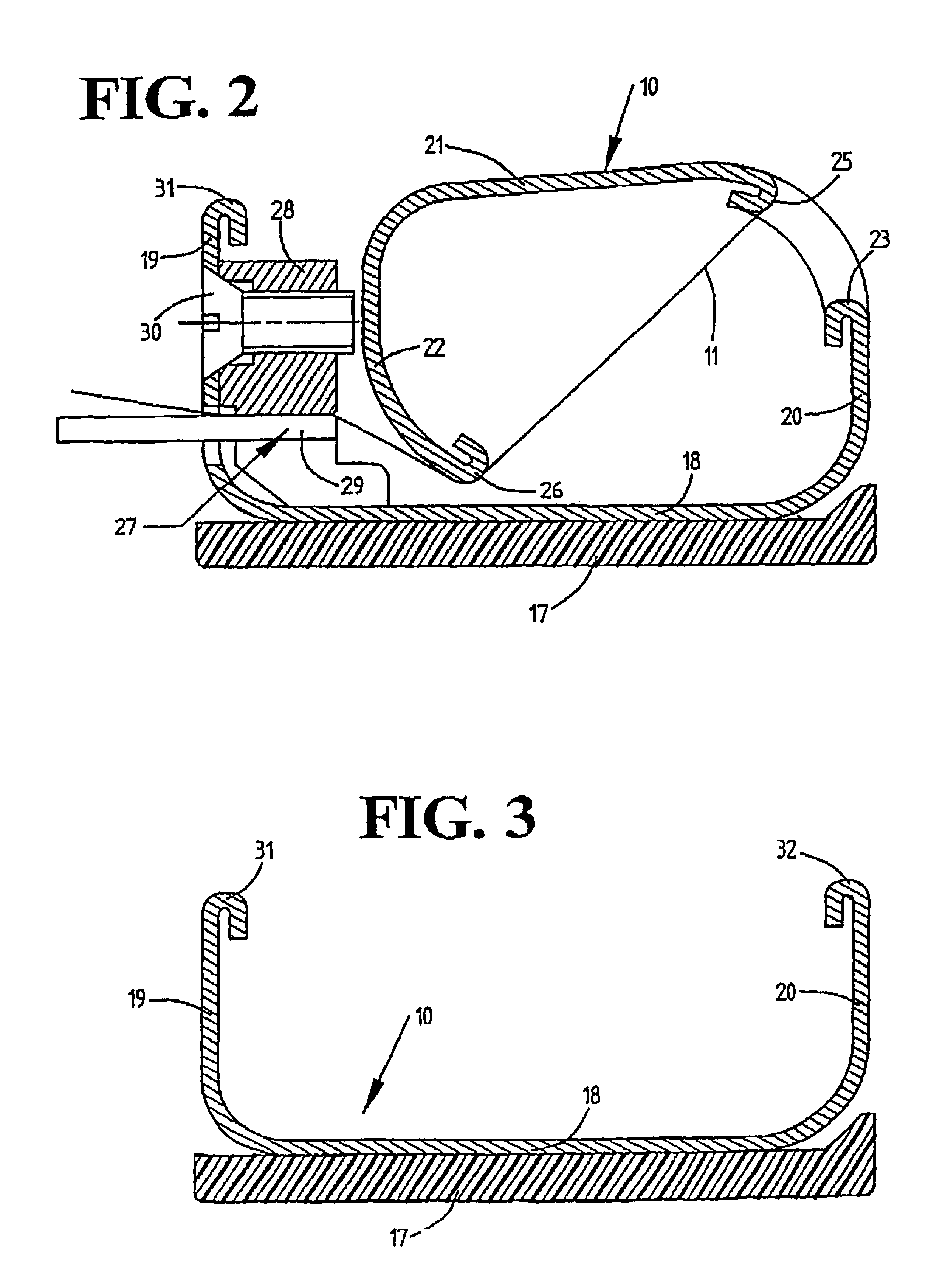
[0019]The drawing gripper 10 shown in FIG. 1 receives a filling 11 kept ready by a feeder element 12 and moves it into a shed 13. The shed 13 is constituted of warps 14, 15 that are raised and lowered. As soon as the drawing gripper 10 has picked up the filling, the latter is severed from the fabric 16. After the filling 11 has been inserted into the shed 13, it will be beaten against the beat-up edge of the fabric 16. Typically the drawing gripper 10 moves the filling into the approximate center of the shed 13. There the filling 11 is accepted by a receiving gripper (not shown) and moved by it to the opposite side. The drawing gripper 10 is affixed to a gripper tape 17 which, by means of a drive that is not shown, and together with the drawing gripper 10, is moved into the shed 13 and then retracted from it.
[0020]The drawing gripper 10 comprises a basic structure consisting of sheetmetal, in particular steel sheetmetal, that is formed into a substantially tubular housing. The cross...
PUM
 Abstract
Description
Claims
Application Information
 - R&D
- Intellectual Property
- Life Sciences
- Materials
- Tech Scout
- Unparalleled Data Quality
- Higher Quality Content
- 60% Fewer Hallucinations
Browse by: Latest US Patents, China's latest patents, Technical Efficacy Thesaurus, Application Domain, Technology Topic, Popular Technical Reports.
© 2025 PatSnap. All rights reserved.Legal|Privacy policy|Modern Slavery Act Transparency Statement|Sitemap|About US| Contact US: help@patsnap.com


