Ceiling air passage system for vehicle air conditioner

a vehicle air conditioner and air passage system technology, applied in the direction of roofs, ducting arrangements, transportation and packaging, etc., can solve the problem of not giving passengers comfortable wind feeling, and achieve the effect of uniform air conditioning feeling, small air blowing speed, and uncomfortable wind feeling

Inactive Publication Date: 2005-08-02
DENSO CORP
View PDF10 Cites 5 Cited by
  • Summary
  • Abstract
  • Description
  • Claims
  • Application Information

AI Technical Summary

Benefits of technology

[0009]According to the present invention, a ceiling air passage system for a vehicle air conditioner having an air conditioning unit includes a passage member for defining an air passage into which conditioned air from the air conditioning unit is introduced, a three-dimension structure member having a three-dimensional passage shape. In the ceiling air passage system, the air passage is provided along a surface of a vehicle ceiling portion, the three-dimension structure member is disposed in the air passage, and the passage member for defining a lower part of the air passage is provided with innumerable air outlets from which the conditioned air in the air passage is blown downward in the passenger compartment. Accordingly, the conditioned air, introduced into the air passage, is distributed in various directions while passing through three-dimension fine passages of the three-dimension structure member. Therefore, the conditioned air can be blown from the innumerable air outlets at a relatively uniform speed in a wide area where the air passage is provided. As a result, relatively uniform air-conditioning feeling can be given to the upper half body of each passenger on the passenger seats in the passenger compartment.
[0010]The ceiling air passage system can be effectively used for a vehicle having a rectangular sunroof opening. In this case, for example, the air passage is provided to enclose an entire periphery of the rectangular sunroof opening of the vehicle. Alternatively, the air passage is provided to enclose three edges of the rectangular sunroof opening. Alternatively, the air passage is provided at a vehicle rear side of the rectangular sunroof opening. Accordingly, the ceiling opening function using the sunroof opening can be exhibited while the air passage can be provided. Further, because the air passage can be provided in a substantially entire area of the ceiling portion except for the sunroof opening, the air outlets can be provided in a wide area of the vehicle ceiling portion. Therefore, conditioned air from the air conditioning unit can be blown from the air outlets by a very small air-blowing speed, and uncomfortable wind feeling is not given to a passenger. Thus, mild and comfortable air-conditioning feeling can be given to the upper half body of the passenger on each passenger seat.

Problems solved by technology

Therefore, conditioned air from the air conditioning unit can be blown from the air outlets by a very small air-blowing speed, and uncomfortable wind feeling is not given to a passenger.

Method used


Image

  • Ceiling air passage system for vehicle air conditioner
  • Ceiling air passage system for vehicle air conditioner
  • Ceiling air passage system for vehicle air conditioner

Examples


first embodiment

[0027](First Embodiment)

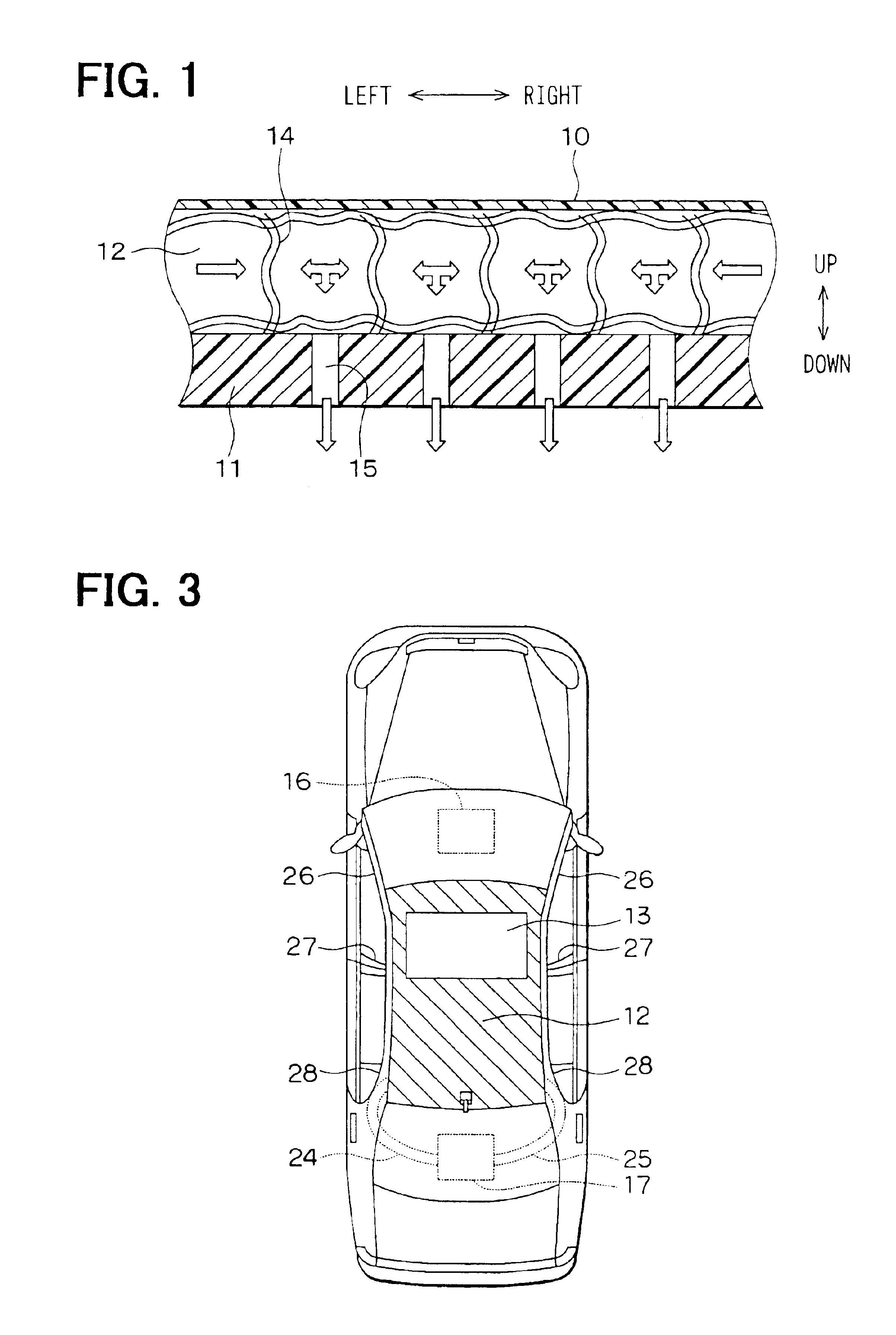
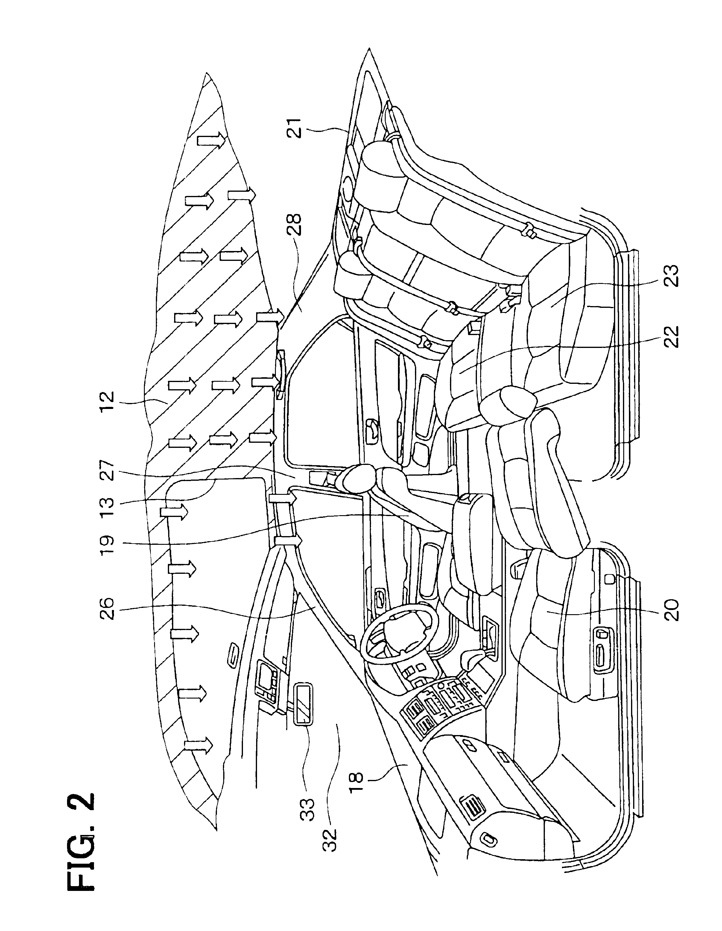
[0028]The first embodiment of the present invention will be now described with reference to FIGS. 1-4. As shown in FIG. 1, a ceiling portion of a vehicle includes a heat insulating member 10 disposed at a lower side (back side) of a vehicle roof (not shown). The heat insulating member 10 is a sheet made of a resin material having high heat-insulating performance and high sealing performance. A ceiling base member 11 is disposed at a lower side of the heat insulating member 10 to have a predetermined distance therebetween. The ceiling base member 11 is made of a resin, and has a thickness much thicker than a thickness of the heat insulating member 10. A base plate of the ceiling portion in a passenger compartment shown in FIG. 2 is constructed with the ceiling base member 11. The predetermined distance is provided between the heat insulating member 10 at the upper side and the ceiling base member 11 at the lower side, thereby providing an air passage 12 betwee...

second embodiment

[0037](Second Embodiment)

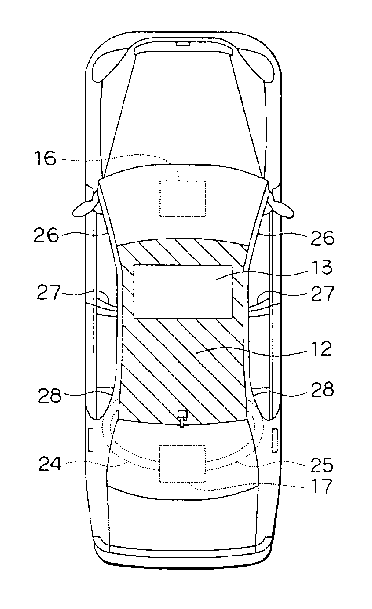
[0038]In the above-described first embodiment, the air passage (slant line area in FIG. 3) 12 is provided so as to enclose the entire periphery of the rectangular sunroof opening 13. However, in the second embodiment, as shown in FIG. 5, the air passage 12 is provided in a U-shape so as to enclose the three edges of the rectangular sunroof opening 13. Specifically, since the sunroof opening 13 is located at a front side of the ceiling portion in the vehicle front-rear direction, the air passage 12 is provided in the U-shape so as to enclose the rectangular sunroof opening 13 at two edges in the vehicle right-left direction and at one edge on the vehicle rear side. In the second embodiment, the other parts are similar to those of the above-described first embodiment, and the advantages similar to the above-described first embodiment can be obtained.

third embodiment

[0039](Third Embodiment)

[0040]In the above-described first and second embodiments, conditioned air is blown from only the air outlet portion of the rear air conditioning unit 17 into the air passage 12 through the right and left air ducts 25, 24. However, in the third embodiment, as shown in FIG. 6, right and left air ducts 25A, 24A communicating with the air passage 12 are provided to be connected to an air outlet portion of the front air conditioning unit 16. The right and left air ducts 25A, 24A are disposed in the A pillars 26 that are located at the most front side among the A pillars 26, the B pillars 27 and the C pillars 28. The right and left air ducts 25A, 24A extend upward to the ceiling portion, so that top ends of the right and left air ducts 25A, 24A are connected to the right and left ends of the air passage 12 in the ceiling portion on the vehicle front side.

[0041]In the third embodiment, since the conditioned air can be blown into the air passage 12 from both of the ...


PUM


Abstract

A ceiling air passage system for a vehicle air conditioner has an air passage into which conditioned air from an air conditioning unit is introduced, a three-dimension structure member having a three-dimension passage shape. The air passage is provided along a vehicle ceiling portion, and the three-dimension structure member is disposed substantially in an entire area of the air passage. Further, a passage member for defining a lower part of the air passage is provided with innumerable air outlets from which conditioned air in the air passage is blown downward in the passenger compartment. Accordingly, the conditioned air can be relatively uniformly blown in a wide area of the vehicle ceiling portion.

Description

CROSS-REFERENCE TO RELATED APPLICATION[0001]This application is related to and claims priority from Japanese Patent Application No. 2002-315916 filed on Oct. 30, 2002, the content of which is hereby incorporated by reference.BACKGROUND OF THE INVENTION[0002]1. Field of the Invention[0003]The present invention relates to a ceiling air passage system for vehicle air-conditioning. The ceiling air passage system includes three-dimension passage structure, and innumerable ceiling air outlets from which conditioned air is blown downward in a passenger compartment.[0004]2. Description of Related Art[0005]For example, in JP-U-62-3310, a ceiling air passage system for a vehicle air conditioner includes a large number of ceiling air outlets from which conditioned air is blown downward in a passenger compartment. Specifically, an upper plate is disposed at a lower side of a vehicle roof, and a lower plate is disposed at a lower side of the upper plate while a predetermined clearance is provide...

Claims


Application Information

Patent Timeline
Patent Type & Authority Patents(United States)
IPC IPC(8): B60H1/00B60H1/24B60H1/34F24F13/02
CPCB60H1/0055B60H1/00564B60H1/245
Inventor UMEBAYASHI, MAKOTO
Owner DENSO CORP
Why Eureka
Try Eureka