Method and apparatus for blending process materials

a technology of process materials and blending equipment, applied in the direction of process and machine control, instruments, transportation and packaging, etc., can solve the problem of rendering the material useless for its intended application

Inactive Publication Date: 2005-08-02
MEGA FLUID SYST
View PDF44 Cites 88 Cited by
  • Summary
  • Abstract
  • Description
  • Claims
  • Application Information

AI Technical Summary

Benefits of technology

[0013]In another embodiment, the present invention is directed to a method of supplying blended process materials. The method includes supplying a plurality of process materials through a plurality of material supply lines and blending the plurality of process materials in a static mixer positioned downstream of the plurality of material supply lines. The method also includes regulating the supply of the plurality of process materials with a process control system including a controller, an input device, and a first valve connected to one of the plurality of material supply lines and to the controller. The input device is conn

Problems solved by technology

In this type of system, each process material is added individually, as an automated control system measuring the mass of the holding vessel is not able to discern the relative amounts of two process materials ad

Method used


Image

  • Method and apparatus for blending process materials
  • Method and apparatus for blending process materials
  • Method and apparatus for blending process materials

Examples


example 1

[0083]A typical blend process includes the dilution of a high solids, concentrated silica slurry with DI water. One such commercially available slurry is the CABOT® SEMI-SPERSE™ 25 slurry, which is a colloidal suspension having 25 wt. % solids and a density range of 1.162-1.170 g / ml (1.166±0.004 g / ml). This slurry is a typical polishing slurry in wafer production used during the silica oxide layer, or oxide step, polish. For purposes of this example, the demand is assumed to be 200 milliliters per minute (ml / min) of the blended process materials.

[0084]Typical polishing processes require a blend having a slurry to DI water ratio of 1:1 by mass or about 1:1.17 by volume, resulting in a final density of about 1.074 grams per milliliter (g / ml). Variations in the slurry may result from variations in the manufacturing of the base material. Furthermore, although an incompressible fluid, the density of water used in the manufacturing of the raw slurry also varies as does the density of the ...

example 2

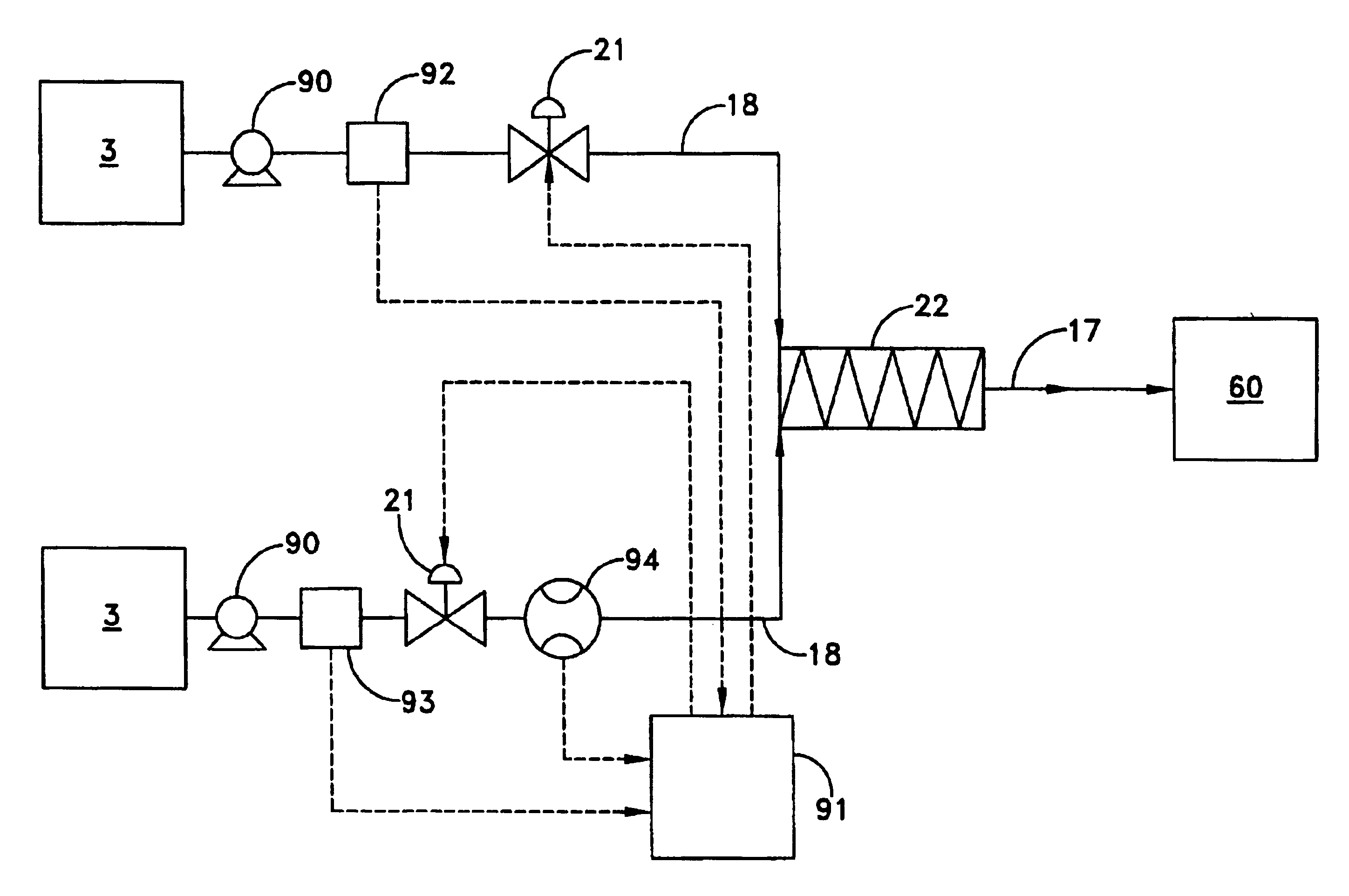
[0088]In order to demonstrate that the blending system of the present invention could produce acceptable blends of process material, the hypothetical blend of slurry and DI water described in Example 1 was performed using the blending system illustrated in FIG. 9. DI water was supplied from a holding vessel at a constant, known volumetric flow rate and its temperature was monitored and supplied to a controller that calculated a mass flow rate of the DI water. The slurry described in Example 1 was supplied from a second holding vessel. This slurry was tested and found to have a percent solids of 25.8 wt. % and a density of 1.151 g / ml. The density of the slurry and its volumetric flow rate were monitored and provided to a controller to calculate a mass flow rate of slurry. The slurry mass flow rate was adjusted with a valve by the controller to produce about a 1:1 mass ratio of DI water to slurry.

[0089]Based on typical error tolerances for the semiconductor industry, a range of accept...


PUM

PropertyMeasurementUnit
Concentrationaaaaaaaaaa
Densityaaaaaaaaaa

Abstract

A method and apparatus for blending and supplying process materials. The method and apparatus are particularly applicable to the blending of ultra-high purity chemicals, the blending of abrasive slurries with other chemicals for the polishing of semiconductor wafers, and high-accuracy blending of chemicals. The apparatus may include a dispensing subsystem that supplies process materials to a mixing subsystem where they are blended with a static mixer. The method may include supplying process materials with a dispensing subsystem and blending the process materials in a static mixer.

Description

[0001]This patent application claims priority to U.S. Provisional Patent Application No. 60 / 222,124, filed Jul. 31, 2000.BACKGROUND OF THE INVENTION[0002]1. Field of Invention[0003]The present invention is directed to a method and apparatus for blending process materials and, particularly, to a method and apparatus for blending ultra-high purity chemicals, abrasive slurries and the like.[0004]2. Description of the Related Art[0005]Blended process materials are required, for example, in the pharmaceutical, cosmetic and semiconductor industries. In the semiconductor industry, blended process materials are typically prepared using batch production systems including a dispensing subsystem and a mixing subsystem. The dispensing subsystem transfers materials from a supply source to the mixing subsystem. Supply sources are typically containers designed for safe storage of a process material, such as a chemical or slurry. Other supply sources include facility generation plants, such as deio...

Claims


Application Information

Patent Timeline
IPC IPC(8): B01F15/04B01F5/06B01F5/04G05D11/00G05D11/13B01F3/08B01F5/00
CPCB01F5/0451B01F5/0646B01F5/0652B01F15/0022B01F15/00233B01F15/0408B01F15/0479G05D11/135B01F3/08B01F2215/0045B01F2215/0096B01F23/40B01F25/3131B01F25/4335B01F25/433B01F35/2134B01F35/2132B01F35/82B01F35/883B01F2101/27B01F2101/58B01F35/80
Inventor WILMER, JEFFREY ALEXANDERMACKENZIE, DANIEL KASELULL, JOHN MICHAELZADAI, ERIC A.WALKER, MICHAEL LOREN
Owner MEGA FLUID SYST
Why Eureka
Try Eureka