Spindle device of machine tool

a technology of machine tools and spindles, which is applied in the direction of turning machine accessories, manufacturing tools, transportation and packaging, etc., can solve the problems of unusual wear and tear of tools, and achieve the effect of preventing effective liquefaction of coolant mists

Inactive Publication Date: 2005-08-02
HORKOS
View PDF10 Cites 13 Cited by
  • Summary
  • Abstract
  • Description
  • Claims
  • Application Information

AI Technical Summary

Benefits of technology

[0007]Besides, the cross-sectional area of the mist outlet passage from the mist outlet member to the rear end of the tool comes not to be changed at each different position in its longitudinal direction greatly. Therefore, the coolant mists in the mist outlet passage are effectively prevented from being liquefied by pressure change.
[0008]Moreover, thanks to the mist outlet member, the coolant mists leaked from the rotary joint are prevented from flowing into an interfitted hole of the tool holder through the inside hole of the spindle. Here, an in-spindle interfitting part is inserted into the interfitted hole. Besides, since the inside hole of the tool holder is airtightly communicated with the mist guiding extension member, the coolant mists are prevented from flowing into the interfitted hole.
[0011]According to this, a through hole of the tool position engaging means conventionally provided in the tool holder feeds coolant mists to the rear end of the tool certainly. Besides, the through hole is airtightly communicated with the mist outlet passage of the mist guiding extension member by the sealing member, and the mist guiding extension member is extracted from or inserted in the through hole easily.
[0015]Besides, mist passages of the mist outlet member, the pressing tube member, the rotary joint and the mist guiding extension member are arranged in line and the diameter in the longitudinal direction forms an almost fixed size. According to this, the cross-sectional area of a mist outlet passage does not much change at the different position of the mist outlet passages in the longitudinal direction. Further, since the mist outlet passages of the mist outlet member, the pressing tube member, the rotary joint and the mist guiding extension member are arranged in line, coolant mists flowing in the mist outlet passages cease to cause pressure change. Therefore, the liquefaction of coolant mists is prevented effectively.

Problems solved by technology

Accordingly, the quality of machining drops and unusual wear of a tool is caused.

Method used


Image

  • Spindle device of machine tool
  • Spindle device of machine tool
  • Spindle device of machine tool

Examples


Embodiment Construction

[0018]The invention will be described with reference to the drawings.

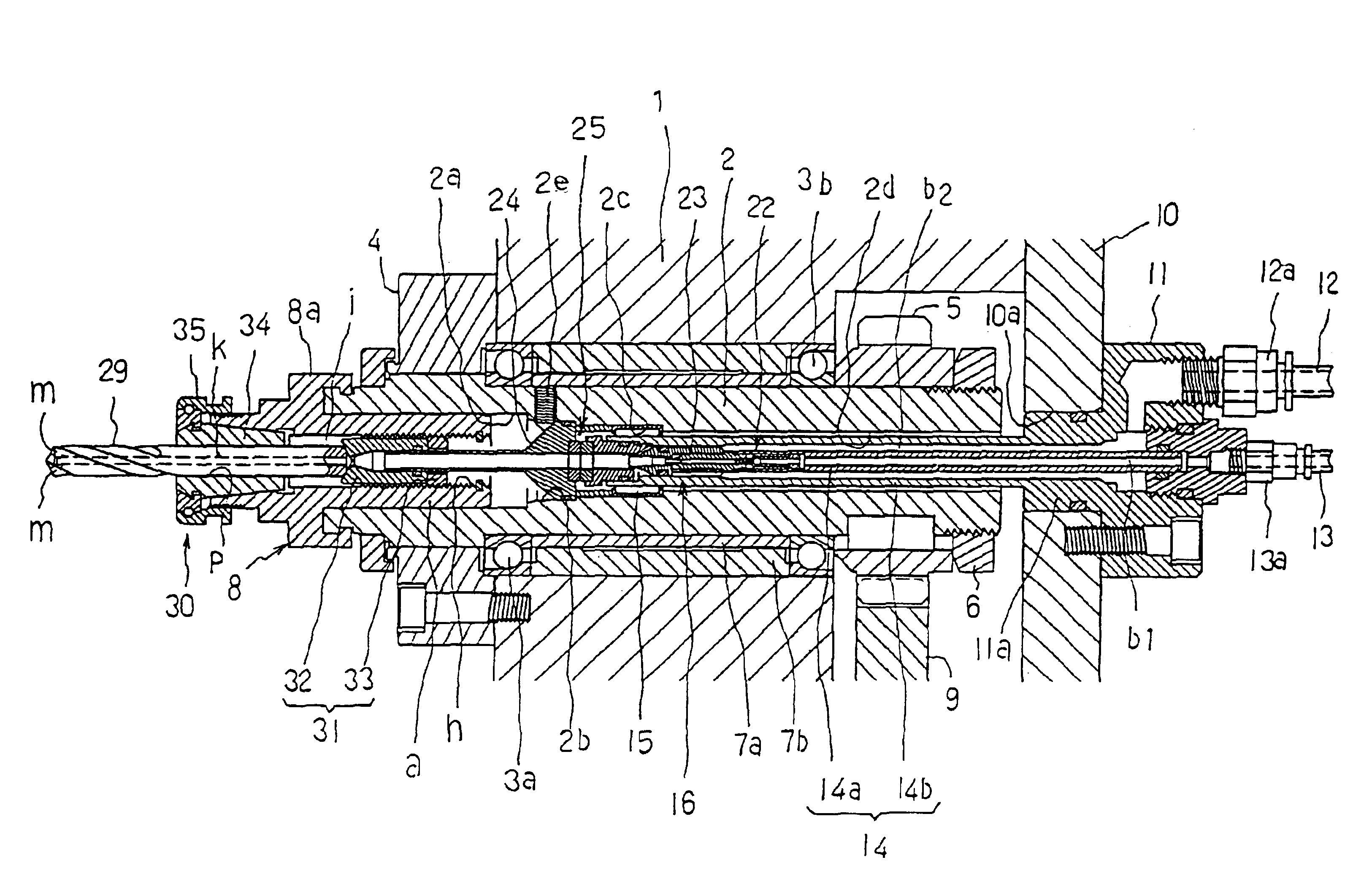
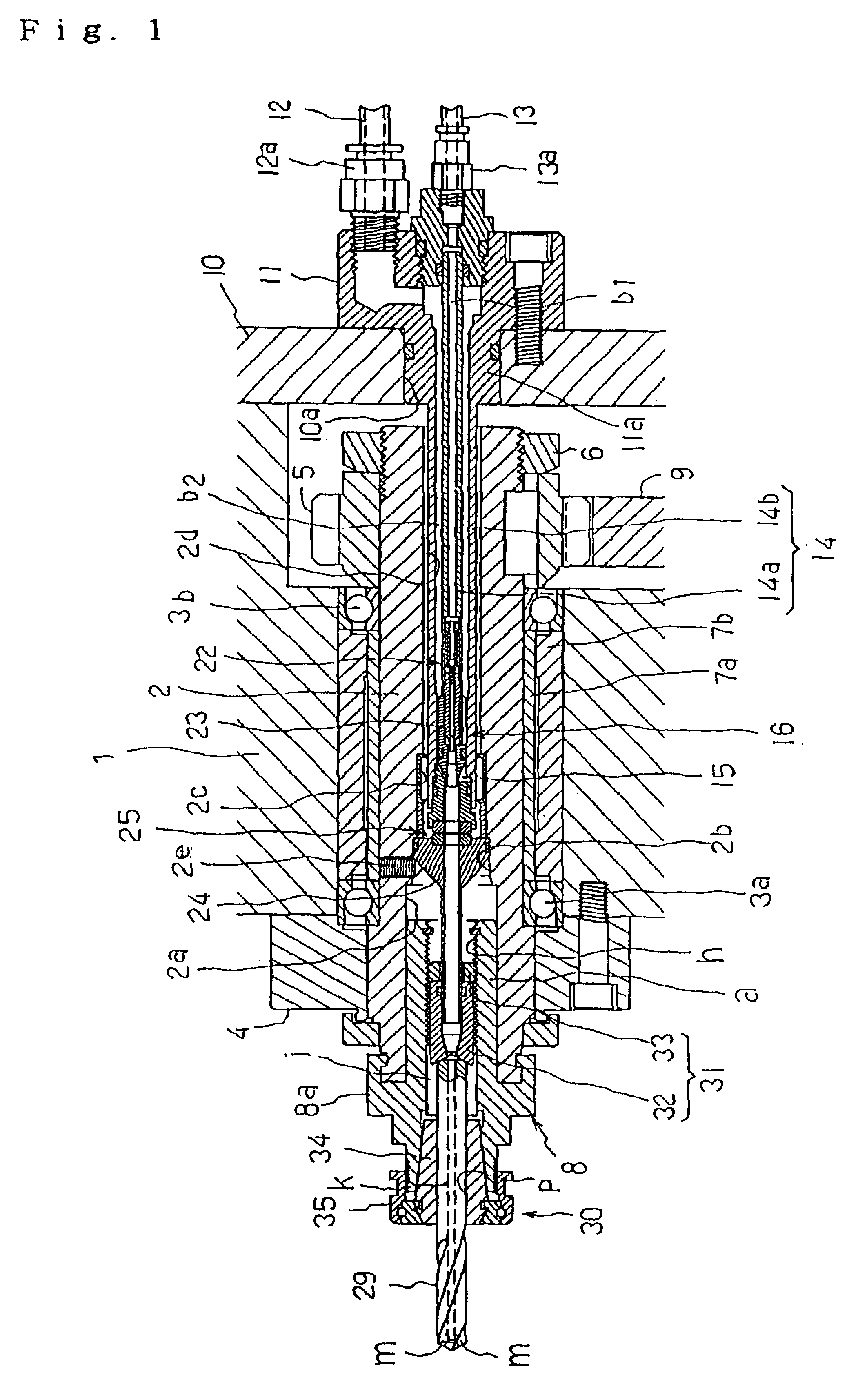
[0019]In these drawings, 1 is a main body frame of a spindle device, and therein, a spindle 2 is inserted through ball bearings 3a, 3b rotatively at a fixed position.

[0020]In this case, 4 is a ring member bolted to the front surface of the frame 1 fixedly, and 5 is an input gear inserted and key-fixed to the rear end of the spindle 2 externally. Numeral 6 is a nut body for regulating the input gear 5 from getting out of the spindle 2, screwed into the rear end of the spindle 2. Numeral 7a, 7b are cylindrical spacers for regulating the longitudinal positions of the ball bearings 3a, 3b.

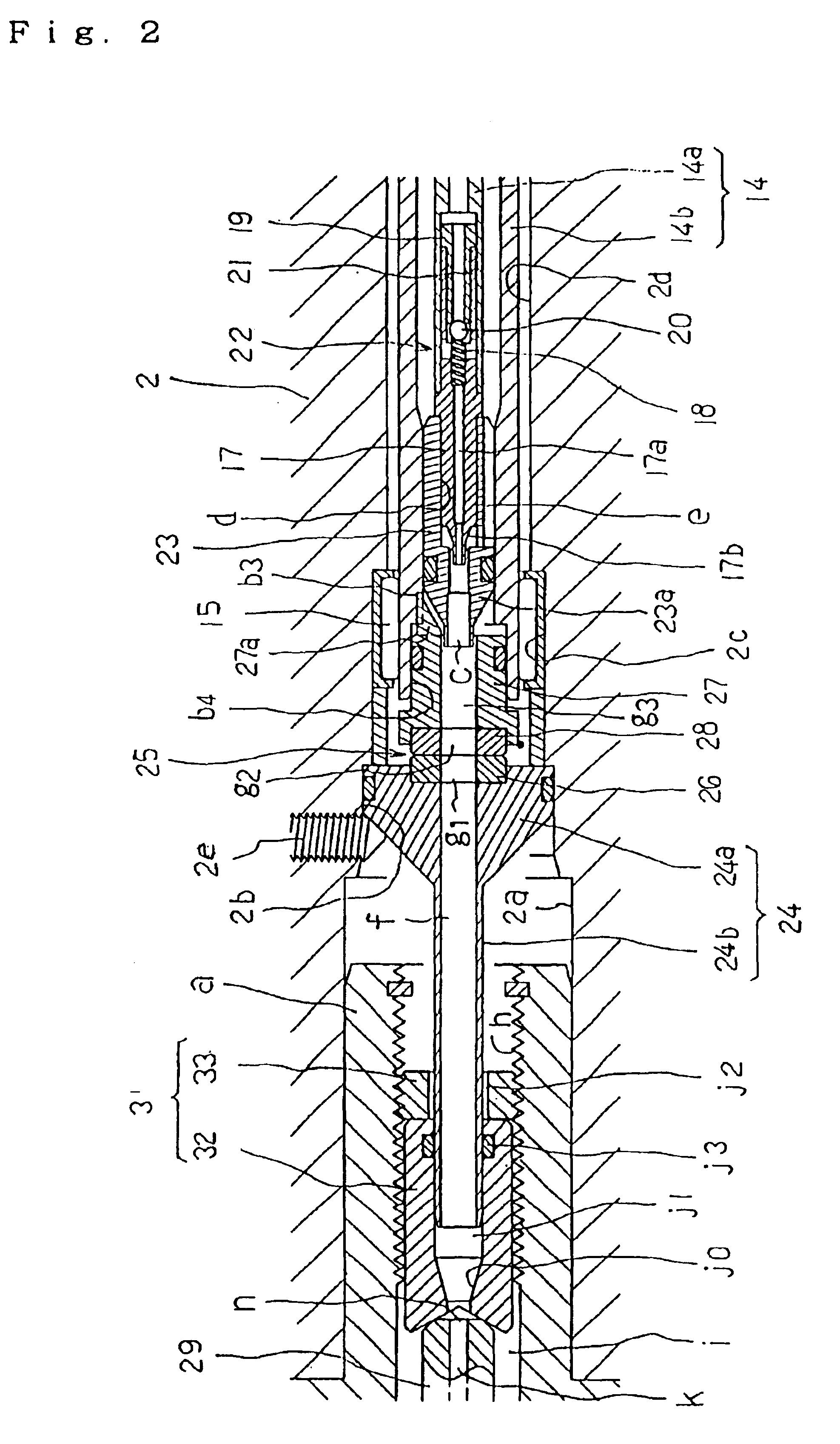
[0021]The spindle 2 has an interfitted hole 2a with a straight tubular surface at the tip center thereof and three straight center holes 2b, 2c, 2d in uneven diameter to the interfitted hole 2a continuously. Numeral 8 is a tool holder consisting chiefly of a holder main body part 8a, and an in-spindle interfitting part, which is a pa...


PUM

PropertyMeasurementUnit
diametersaaaaaaaaaa
sizeaaaaaaaaaa
diameteraaaaaaaaaa

Abstract

A spindle device of a machine tool capable of preventing coolant mist from being excessively liquefied in an area between a mist outlet member 23 and near the rear end part of a tool 29, wherein a straight feed pipe 14 formed of a double tube having an inside tube 14a and an outside tube 14b is inserted into an inside hole formed at the center part of a spindle 2 in non-rotating state not coming into contact with the spindle, coolant is fed to the inside tube 14a, compressed air is fed to the outside tube 14b, and a mist generating member 16 is formed of both tubes near the inside tip part of the spindle, a mist outlet member 23 is installed into the outside tube 14b integrally with each on the mist outlet passage c of the mist generating member 16 so as to surround the mist outlet passage and a mist guiding extension member 24 allowed to reach near the rear end part of the tool in the center hole of the tool holder is installed, integrally with the spindle, on the other tool holder 8 side, and the mist guiding passage f of the mist guiding extension member 24 is allowed to communicate with the mist outlet passage c of the mist outlet member 23 through both a rotary joint 25 and a pressing tube member 27.

Description

FIELD OF THE INVENTION[0001]The present invention relates to a spindle device of a machine tool for generating coolant mist in a spindle.BACKGROUND OF THE INVENTION[0002]A machine tool with a spindle device having a mist generating member in a center hole of a spindle driven for rotation has been disclosed in a prior art reference, for example, Japanese Patent No. 2687110 and Japanese Patent Provisional Publication No. 235641 of 1999. As shown therein, coolant mists spouted from a non-rotatable mist outlet member of the mist generating member escape from a tip opening of a tool through a center hole of a tool holder before the mist outlet member.[0003]In this machine tool, the diameter of a mist passage from the front end of the mist outlet member to the rear end of the tool changes in size comparatively greatly, and the mist passage part with comparatively large diameter is rotated together with the spindle. Therefore, coolant mists are liquefied in the mist passage over permissibl...

Claims


Application Information

Patent Timeline
Patent Type & Authority Patents(United States)
IPC IPC(8): B23Q11/10B23Q1/00
CPCB23Q11/1015B23Q11/103B23Q11/1046Y10T408/45Y10T408/46Y10T408/44Y10T408/458Y10T409/304032Y10T408/455Y02P70/10
Inventor SUGATA, SHINSUKEMAKIYAMA, TADASHI
Owner HORKOS
Why Eureka
Try Eureka