Venoscope apparatus

a venoscope and apparatus technology, applied in the field of instruments, can solve the problems of insufficient candle power for properly illuminated areas, difficult task of locating venous structures such as peripheral veins, etc., and achieve the effect of improving the visual field of structures below the skin, effective positioning of subcutaneous structures, and improving the visual field

Inactive Publication Date: 2005-08-02
CREAGHAN JR FR C
View PDF28 Cites 113 Cited by
  • Summary
  • Abstract
  • Description
  • Claims
  • Application Information

AI Technical Summary

Benefits of technology

[0008]The improved apparatus of the present invention solves the problems in the art in a simple manner. What is provided is an improved instrument for viewing subcutaneous venous structure, known as a VENOSCOPE, which includes a principal body, having a first fixed arm extending therefrom, and a second movable arm captured by upper and lower body portions; a plurality of ultra bright red and white LEDs positioned at the end of the first arm, and a second plurality of ultra bright red and white LEDs positioned at the end of the second arm. Preferably the red LEDs would have a wavelength of 700 to 430 nanometers; and the white LEDs having a wavelength range of 460 to 555 nanometers; and a battery positioned within the body for selectively providing electrical energy to the plurality of red and white LEDs, so that a more defined and intensely illuminated field of visualization of the structures below the skin and the surrounding subcutaneous tissue can be defined.
[0009]Therefore, it is a principal object of the present invention to provide an improved VENOSCOPE apparatus, utilizing a combination of ultra bright red and white LED's to more effectively locate subcutaneous structures, such as veins, below the skin;
[0010]It is a further object of the present invention to provide a light-weight, compact, battery powered VENOSCOPE that improves the visual field of structures below the skin with the use of a combination of ultra bright LEDs;
[0011]It is a further object of the present invention to provided an improved VENOSCOPE apparatus, which through the use of a combination of enhanced red and white light fields provides a visual field that is more greatly enhanced and improves the task of locating structures below the skin;
[0012]It is a further object of the present invention to provide an improved VENOSCOPE apparatus, where the red and white LEDs have differing and varying wavelengths so as to achieve a greater penetration of the subcutaneous tissue and achieve a greater contrast with the blood vein;
[0013]It is a further object of the present invention to provide an improved VENOSCOPE apparatus, where the red LEDs provide deeper penetration into the subcutaneous tissue and the white LEDs provides contrast between the subcutaneous tissue in order to present the blood vein as a dark line within the tissue between the arms of the device.

Problems solved by technology

In the medical field, the task of locating venous structures, such as peripheral veins, is a difficult task.
The drawback in this device was the fact that the lights at that state of the art could not produce the necessary candle power to properly illuminate the area.

Method used


Image

  • Venoscope apparatus
  • Venoscope apparatus
  • Venoscope apparatus

Examples


Embodiment Construction

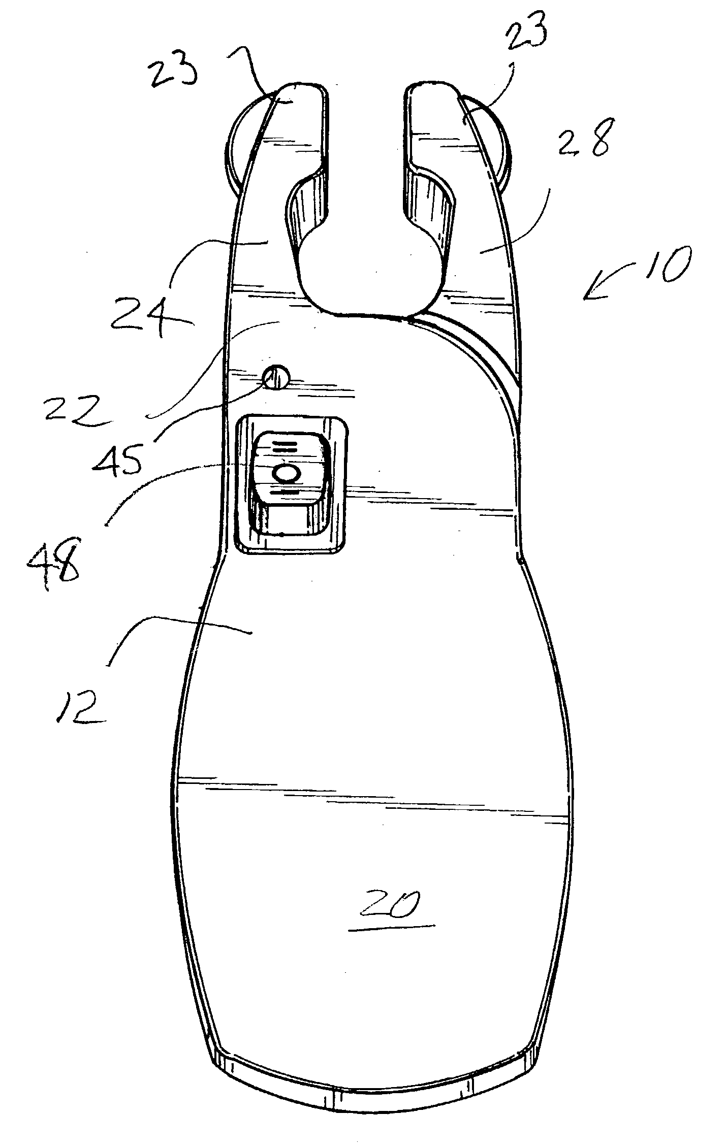
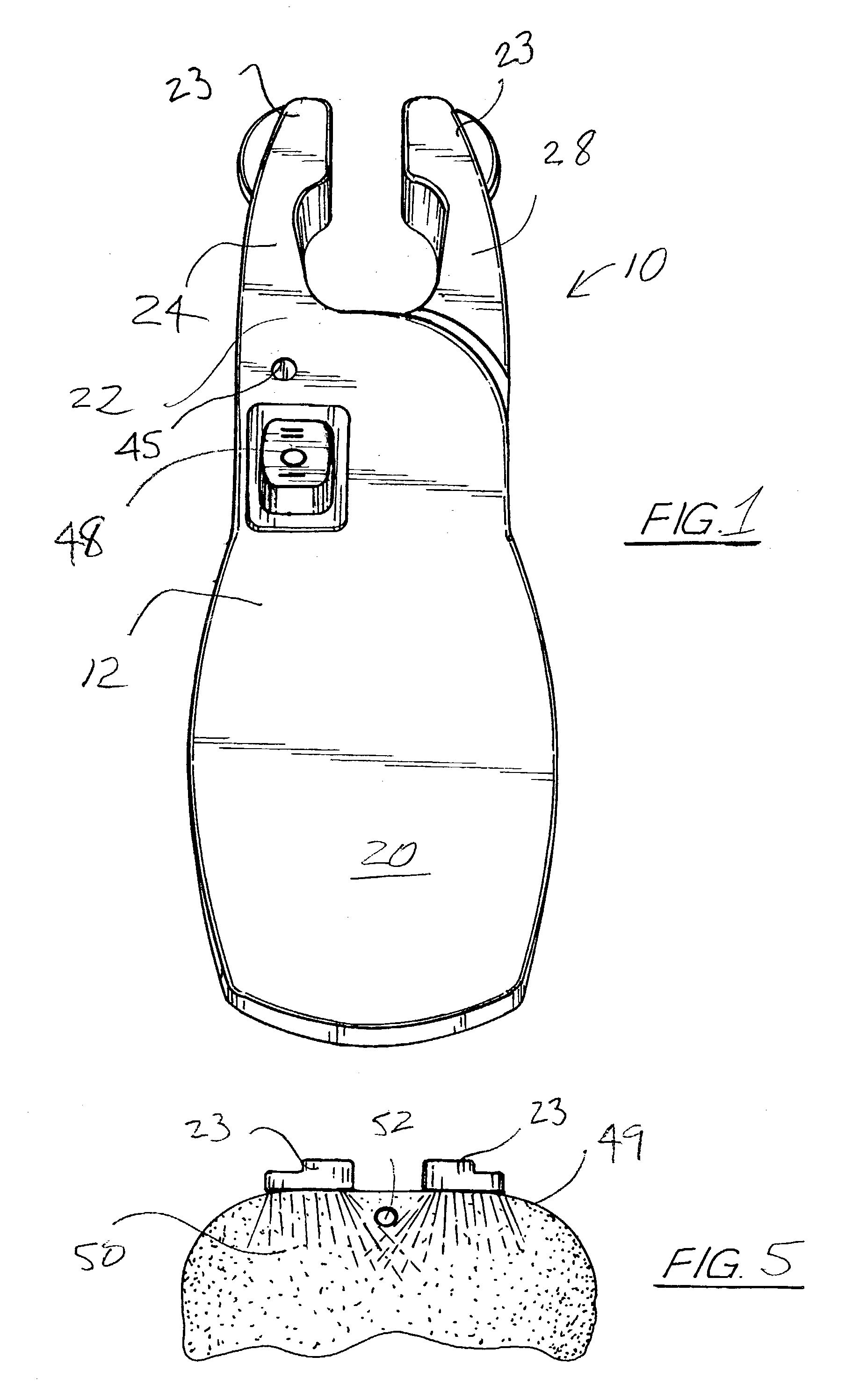
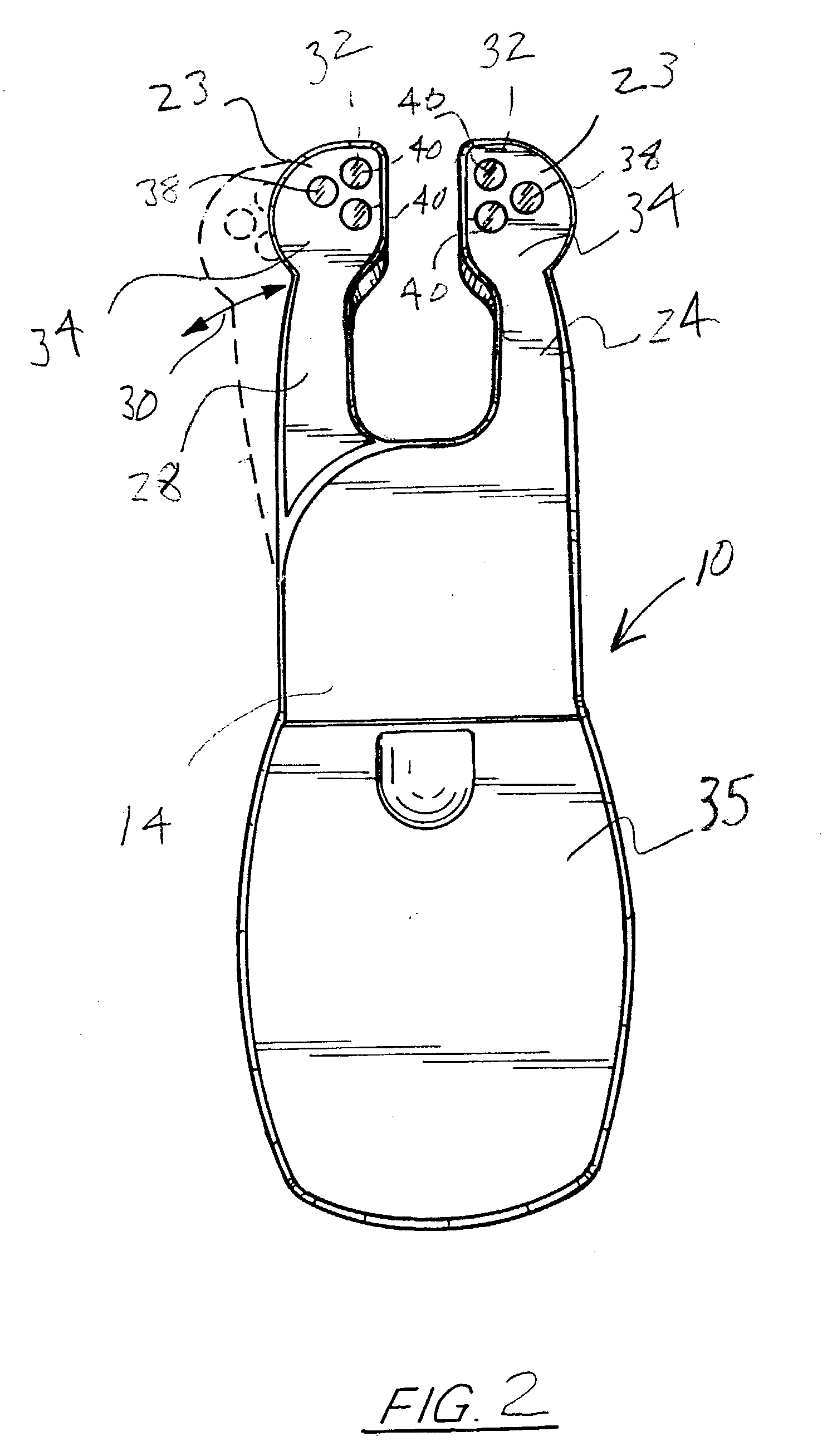
[0022]FIGS. 1 through 5 illustrate the preferred embodiment of the improved VENOSCOPE apparatus 10 of the present invention. VENOSCOPE is a trademark owned by Venoscope, L.L.C. As illustrated in FIGS. 1 through 3, apparatus 10 in overall view provides a principal body 12, having an upper body portion 14, and a lower body portion 16, the two body portions 14, 16 secured along a common edge 18 to define the complete principal body 12 when portions 14, 16 are assembled. As further illustrated, a first rear end of the housing 12 provides an area 20 for grasping the apparatus, while in use, and the second end 22, terminates in a first fixed arm portion 24. Upper body portion 14 further provides a means internal to the body portion for allowing a second moveable arm portion 28 to be moveably secured between housings 14, 16, for allowing movement of the arm 28 in the direction of arrow 30 in FIG. 2.

[0023]As seen further in FIG. 2, the distal ends 23 of the arms 24, 28 include a plurality o...


PUM


Abstract

An improved instrument for viewing subcutaneous venous structure, known as a VENOSCOPE, which includes a clamshell housing, having a first fixed arm extending therefrom, and a second movable arm captured by upper and lower portions of the housing; a first high intensity plurality of white and red LEDs positioned at the end of the first arm, and a second high intensity plurality of high intensity red and white LED positioned at the end of the second arm, and a battery positioned within the housing for selectively provided electrical energy to the red and white LEDs, so that a more defined and intensely illuminated field of visualization between structures below the skin and the surrounding subcutaneous tissue is defined. Additional embodiments include a tube or handle connected to a head having multiple arms or a single arm with multiple LEDs.

Description

CROSS-REFERENCE TO RELATED APPLICATIONS[0001]Priority of U.S. Provisional Patent Application Ser. No. 60 / 334,821, filed Nov. 1, 2001, incorporated herein by reference, is hereby claimed.STATEMENT REGARDING FEDERALLY SPONSORED RESEARCH OR DEVELOPMENT[0002]Not applicableREFERENCE TO A “MICROFICHE APPENDIX”[0003]Not applicableBACKGROUND OF THE INVENTION[0004]1. Field of the Invention[0005]The apparatus of the present invention relates to instruments for viewing subcutaneous venous structures.[0006]2. General Background of the Invention[0007]In the medical field, the task of locating venous structures, such as peripheral veins, is a difficult task. There have been attempts to make the task less difficult. One such device, which is currently under U.S. Pat. No. RE 33,234, is an instrument which directs a pair of light beams through the ends of a pair of arms pressed against the skin to produce an illuminated field beneath the skin, where peripheral veins can be visualized and located. Th...

Claims


Application Information

Patent Timeline
Patent Type & Authority Patents(United States)
IPC IPC(8): A61B1/06A61B5/00
CPCA61B5/0059A61B5/489A61M5/425A61B2562/0238A61M5/427
Inventor CREAGHAN, JR., FRANK C.
Owner CREAGHAN JR FR C
Why Eureka
Try Eureka