
Damage prevention system for cables, pipelines and the like

a technology of damage prevention and cable, which is applied in the direction of couplings, pipes, instruments, etc., can solve the problems of loss of service, damage to such transmission lines by external forces, excavation, earthquakes, etc., and widespread damag

Inactive Publication Date: 2005-08-02
PAYNE BRIAN L +1
View PDF8 Cites 8 Cited by
  • Summary
  • Abstract
  • Description
  • Claims
  • Application Information

AI Technical Summary

Benefits of technology

[0004]These disadvantages of the prior art are overcome with the present invention and an improved warning, detection and protection system is provided which positively identifies when and where a break, caused by external forces, is likely to occur or has occurred. Often, it will inform the transmission line owner prior to actual rupture of the transmission line, thereby enabling the transmission line operator to prevent rupture of the line and the ensuing damage.
[0006]Accordingly, it is an object of the present invention to provide improved means for protecting a transmission line from external forces.
[0007]Another object of the present invention is to provide means for protecting a transmission line which positively identifies when and where a break is likely to occur or has occurred. Often, it will inform the transmission line owner prior to actual rupture of the transmission line.
[0008]An additional object of the present invention is to provide means for protecting a transmission line which enables the transmission line operator to prevent rupture of the line and the ensuing damage or to minimize said damage by providing the damage location, thereby reducing emergency response times.

Problems solved by technology

However, as a result, damage to such transmission lines by external forces, such as excavation, earthquakes, etc. has also become widespread.
Moreover, each such breakage results in substantial damage due to loss of service, spillage of hazardous materials, explosion, fire, etc.
Actual costs run in the range of $500,000 per incident, with annual costs due to such damage running well into the millions.
These steps reduce, but do not eliminate the problem and many such incidents still occur.
Unfortunately, these laws are often not adhered to by contractors, are not enforced and / or the transmission lines are unmarked or mis-marked.
Consequently, the locations of many transmission lines are unknown and persons digging in the vicinity are unaware of the presence of the transmission line until the transmission line has been damaged or broken and the damage has been done.
If the line is broken, the owner may not be aware of the intrusion unless leak detection systems are installed to detect the leak and create an alarm.
However, most of these systems do not report the location of the intrusion.
If the line is damaged, but does not rupture, the intruder may simply refill the excavation without reporting the damage to the owner, which can result in subsequent leaks or rupture.
This type of incident has resulted in some of our country's most tragic pipeline incidents.
Furthermore, transmission line owners have recently become concerned about threats from terrrorist activity which could jeopardize major energy and data transportation.
Thus, none of the prior art third party damage warning, detecting locating and protection systems have been entirely satisfactory.

Method used


Image

  • Damage prevention system for cables, pipelines and the like
  • Damage prevention system for cables, pipelines and the like

Examples


Embodiment Construction

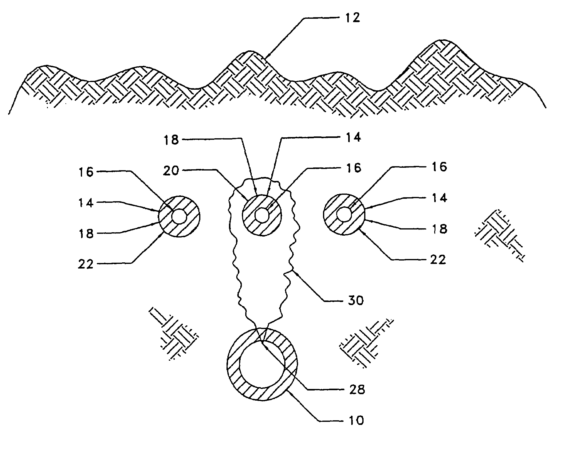
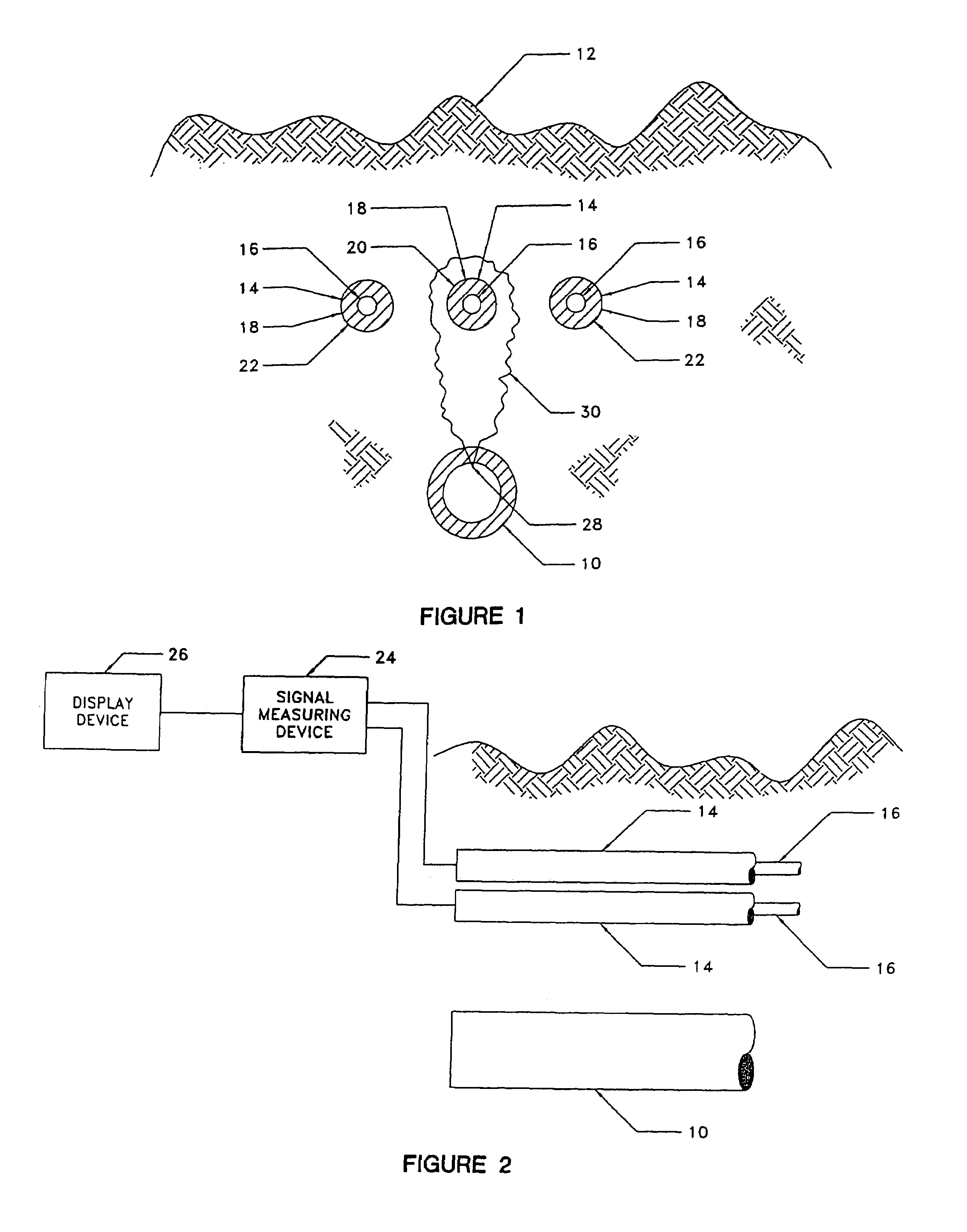
[0013]In that form of the present invention chosen for purposes of illustration, FIG. 1 shows a transmission line, indicated generally at 10, which is buried in the earth 12 and is protected by one or more protective devices 14, in accordance with the present invention, which are buried adjacent, but above and, optionally to the sides of or beneaqth, the transmission line 10 which is to be protected. The protective devices 14 each comprise at least one fiber optic signal carrying core 16 for carrying signals encased within an insulating sheath 18 which protects the core 16 against damage, severance, erosion or other damage by the surrounding earth or the fluids or creatures therein. As seen in FIG. 1, several of the protective devices 14 may be provided. If only one protective device 14 is used, it should be placed directly above and / or spaced laterally from the transmission line 10, as seen at 20 in FIG. 1. It should be understood that, where two or more or the protective devices 1...


PUM


Abstract

A transmission line protection system comprising at least one signal carrying line buried adjacent the transmission line to be protected, means transmitting a signal through said signal carrying line, and means responsive to damage or severance of said signal carrying line to indicate that said signal carrying line has been damaged or severed and the location of the damage or severance.

Description

RELATED CASES[0001]This invention is described in our provisional patent application Ser. No. 60 / 187,417, filed Mar. 7, 2000 and now expired and our utility application Ser. No. 09 / 633,564, filed Aug. 7, 2000 and now abandoned Feb. 17, 2002.FIELD OF INVENTION[0002]This invention relates to underground transmission systems, such as cables, pipe lines and the like and is particularly directed to improved means for detecting, locating and protecting such transmission lines against damage due to external forces and the like.PRIOR ART[0003]The use of underground transmission lines for delivering natural gas, crude oil, chemicals, petroleum products, data, telephone and televisions signals, etc, has become widespread. However, as a result, damage to such transmission lines by external forces, such as excavation, earthquakes, etc. has also become widespread. Approximately one-third of all underground transmission line breakages are caused by such external forces. Moreover, each such breaka...

Claims


Application Information

Patent Timeline
IPC IPC(8): H02G9/00H02G9/02
CPCH02G9/00H02G9/02F16L2201/30
Inventor PAYNE, BRIAN L.WALLS, TERRY L.
Owner PAYNE BRIAN L
Learn More