Method and apparatus for transformer bandwidth enhancement

a transformer and bandwidth technology, applied in the field of communication transformers, can solve the problems of limiting the use of transformers to low or moderate data-rate applications, limiting and often exceedingly difficult to meet requirements at signal frequencies above approximately 200 mhz, etc., to achieve the effect of increasing the bandwidth of communication device transformers

Inactive Publication Date: 2005-08-02
MARVELL ASIA PTE LTD
View PDF1 Cites 19 Cited by
  • Summary
  • Abstract
  • Description
  • Claims
  • Application Information

AI Technical Summary

Benefits of technology

[0017]Yet another method for increasing the bandwidth of a communication device transformer that has a primary winding and a secondary winding is disclosed herein. This method comprises cross-connecting one or more compensation networks to the transformer to establish an all-pass network. The one or more compensation networks may comprise one or more printed circuit board capacitor traces. In addition, the transformer may be in a reverse polarity configuration, thereby eliminating crossed conductors when cross-connecting the one or more compensation networks. In one embodiment, the transformer is in an unbalanced-to-unbalanced coupled configuration.

Problems solved by technology

In systems of the prior art, these requirements are often extremely difficult to meet at signal frequencies above approximately 200 MHz.
This difficulty limits the use of transformers to low or moderate data-rate applications, or limits transmittal speeds.
While these limitations have previously existed, prior transmit speeds did not approach the physical limitations of prior art transformer capabilities.
As a result, prior art transformer designs are unacceptable for high frequency applications.
Both of these proposed solutions, however, have drawbacks that make both them unsuitable for higher frequency data communications applications.
This compensation method is ultimately limited by the value of the transformer leakage inductance.
The transmission line transformer, however, does not provide high-voltage DC isolation, has poor low-frequency common-mode rejection, and is restricted to a small set of feasible turn ratios, as determined by multifilar construction.
As a result, transmission line transformers are not ideally suited for most data communication applications.
However, the first winding and the second winding suffer from flux leakage, and consequently, the signal is also provided to a compensation system to compensate for the flux leakage.

Method used


Image

  • Method and apparatus for transformer bandwidth enhancement
  • Method and apparatus for transformer bandwidth enhancement
  • Method and apparatus for transformer bandwidth enhancement

Examples


Embodiment Construction

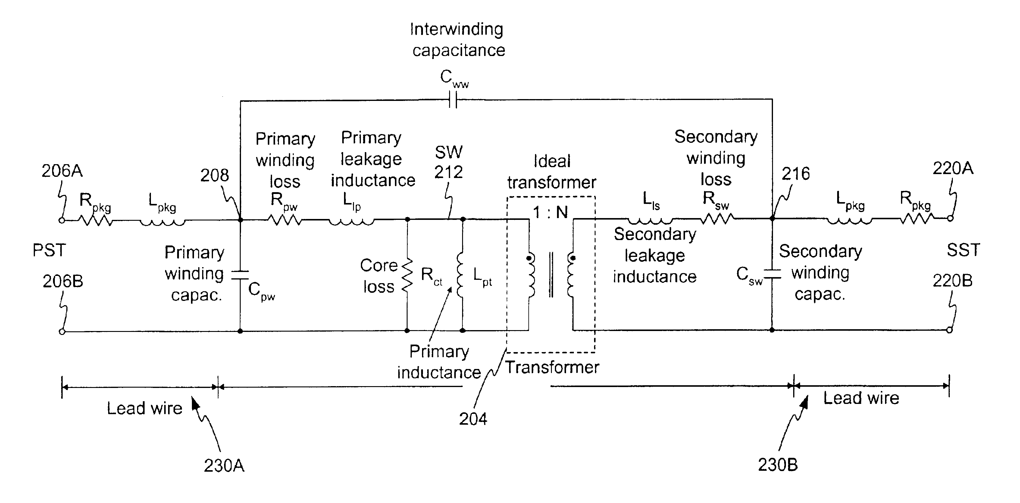
[0033]In general, high-frequency performance limitations in magnetically coupled line transformers are due to parasitic components associated with imperfections in transformer construction. Typical limiting factors are the transformer core—material, geometry, etc., winding construction—winding method, turns ratio, etc., and package construction. As way of introduction to the invention, a typical high frequency transformer circuit model is shown in FIG. 2.

[0034]As shown in FIG. 2, an ideal transformer 204 is shown having a turn ratio of 1:N, where N equals any numeric value. As can be understood, an ideal transformer does not exist, as all transformers have associated parasitic resistances, inductances, and capacitances. Accordingly, FIG. 2 also illustrates the equivalent parasitic resistances, inductances, and capacitances that may be modeled or associated with an actual transformer. Working from the left hand side of the figure, primary side terminals, (PST), 206A, 206B allow for c...


PUM

PropertyMeasurementUnit
frequenciesaaaaaaaaaa
corner frequencyaaaaaaaaaa

Abstract

A method and apparatus for transformer bandwidth enhancement is disclosed. In one embodiment, a transformer is provided for use in a high frequency communication environment. In one configuration, the transformer is configured with one or more compensation networks to improve high frequency operation and to reduce insertion loss at all frequencies. The compensation networks may be designed, in combination with a transformer, to create an equivalent all-pass symmetric lattice network having a frequency response in the desired range. In one embodiment, the compensation networks comprise a capacitance creating device which, when cross-connected to the transformer, increases transformer bandwidth.

Description

FIELD OF THE INVENTION[0001]The invention relates to communication transformers and, in particular, to a method and apparatus for increasing a transformer's high frequency performance.RELATED ART[0002]High-speed data communication systems, such as for example, 1000BaseT systems, often require a line transformer between the transceiver and the physical medium. The transformer provides DC isolation, impedance transformation, common-mode signal suppression, and a safety insulation barrier to meet regulatory safety requirements. To prevent degradation of system performance, it is preferable that the transformer display low insertion loss, thereby maximizing transmit power, and a high return loss, to minimize channel echo effects across a transmit signal's bandwidth.[0003]In systems of the prior art, these requirements are often extremely difficult to meet at signal frequencies above approximately 200 MHz. This difficulty limits the use of transformers to low or moderate data-rate applic...

Claims


Application Information

Patent Timeline
Patent Type & Authority Patents(United States)
IPC IPC(8): H01F19/00H01F19/08H01F27/42
CPCH01F19/08H01F27/42
Inventor GRILO, JORGE ALBERTOCOHEN, LARANCE B.
Owner MARVELL ASIA PTE LTD
Why Eureka
Try Eureka