Oscillation device, optical deflector using the oscillation device, and image display device and image forming apparatus using the optical deflector, and method of manufacturing the oscillation device

a technology of oscillation device and oscillation device, which is applied in the direction of magnets, instruments, magnets, etc., can solve the problems of limiting the cross section of the above-mentioned optical deflector, difficult to further increase the deformation angle, etc., and achieves the effects of enhancing energy efficiency, high speed, and large displacemen

Inactive Publication Date: 2005-08-02
CANON KK
View PDF5 Cites 64 Cited by
  • Summary
  • Abstract
  • Description
  • Claims
  • Application Information

AI Technical Summary

Benefits of technology

[0013]The present invention has been made in order to solve the above-mentioned problems, and an object of the present invention is to provide an oscillation device which is capable of: operating at a high speed with large displacement; enhancing an energy efficiency; being manufactured inexpensively; and oscillating about two axes, an optical deflector using the oscillation device, and an image display device and an image forming apparatus using the optical deflector, and a method of manufacturing the oscillation device.

Problems solved by technology

However, any of the above-mentioned optical deflectors has the following problems.
However, since the core constituting the thin film electromagnet portion 1007 is a thin film formed through the sputtering process, there is a limit to an increase of its cross section.
Hence, it is difficult to further increase the deformation angle.
Thus, if the size of the second movable plate 905 is increased, then it is difficult to expect higher speed operation and more miniaturization.

Method used


Image

  • Oscillation device, optical deflector using the oscillation device, and image display device and image forming apparatus using the optical deflector, and method of manufacturing the oscillation device
  • Oscillation device, optical deflector using the oscillation device, and image display device and image forming apparatus using the optical deflector, and method of manufacturing the oscillation device
  • Oscillation device, optical deflector using the oscillation device, and image display device and image forming apparatus using the optical deflector, and method of manufacturing the oscillation device

Examples


example 1

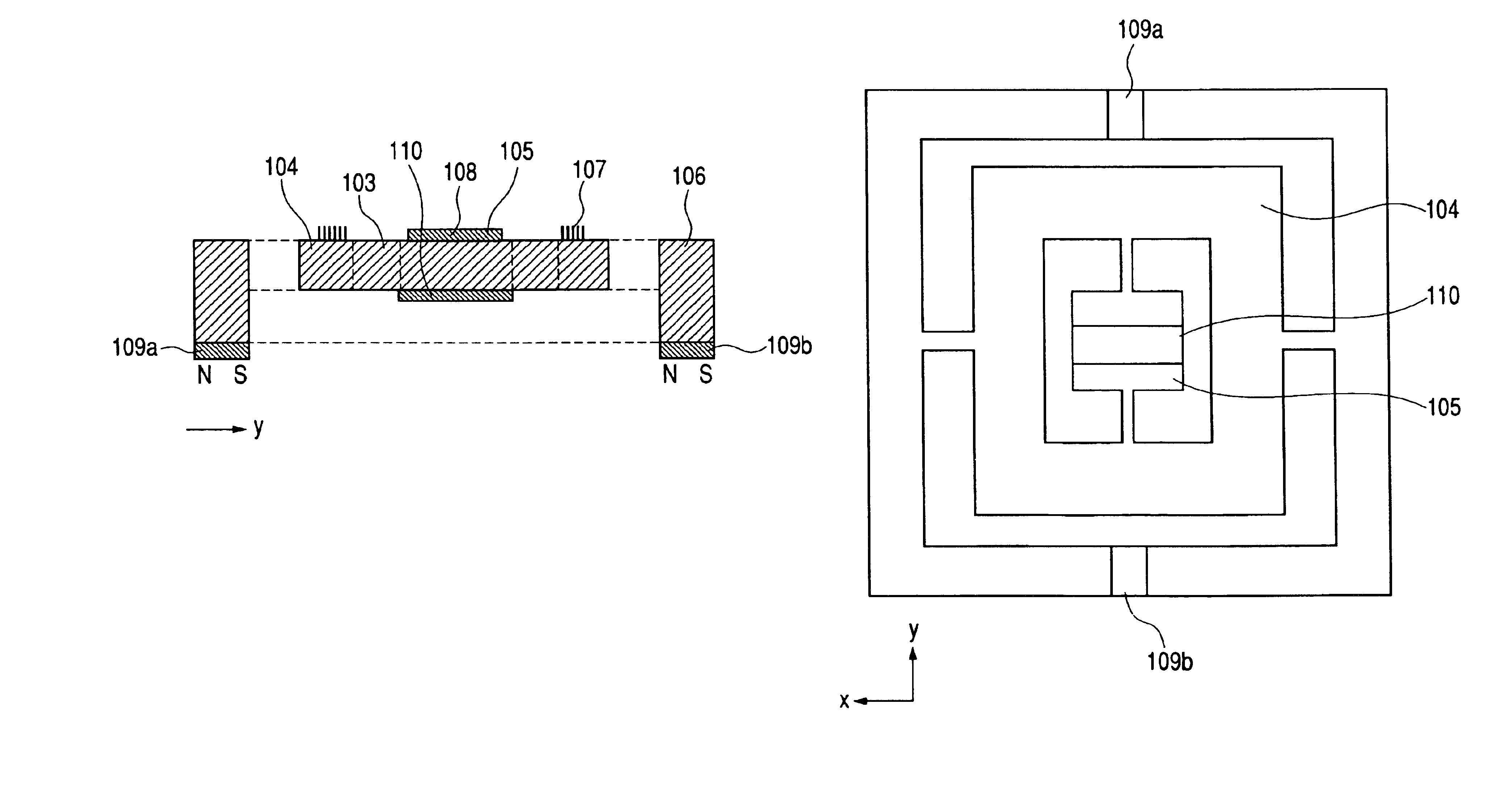
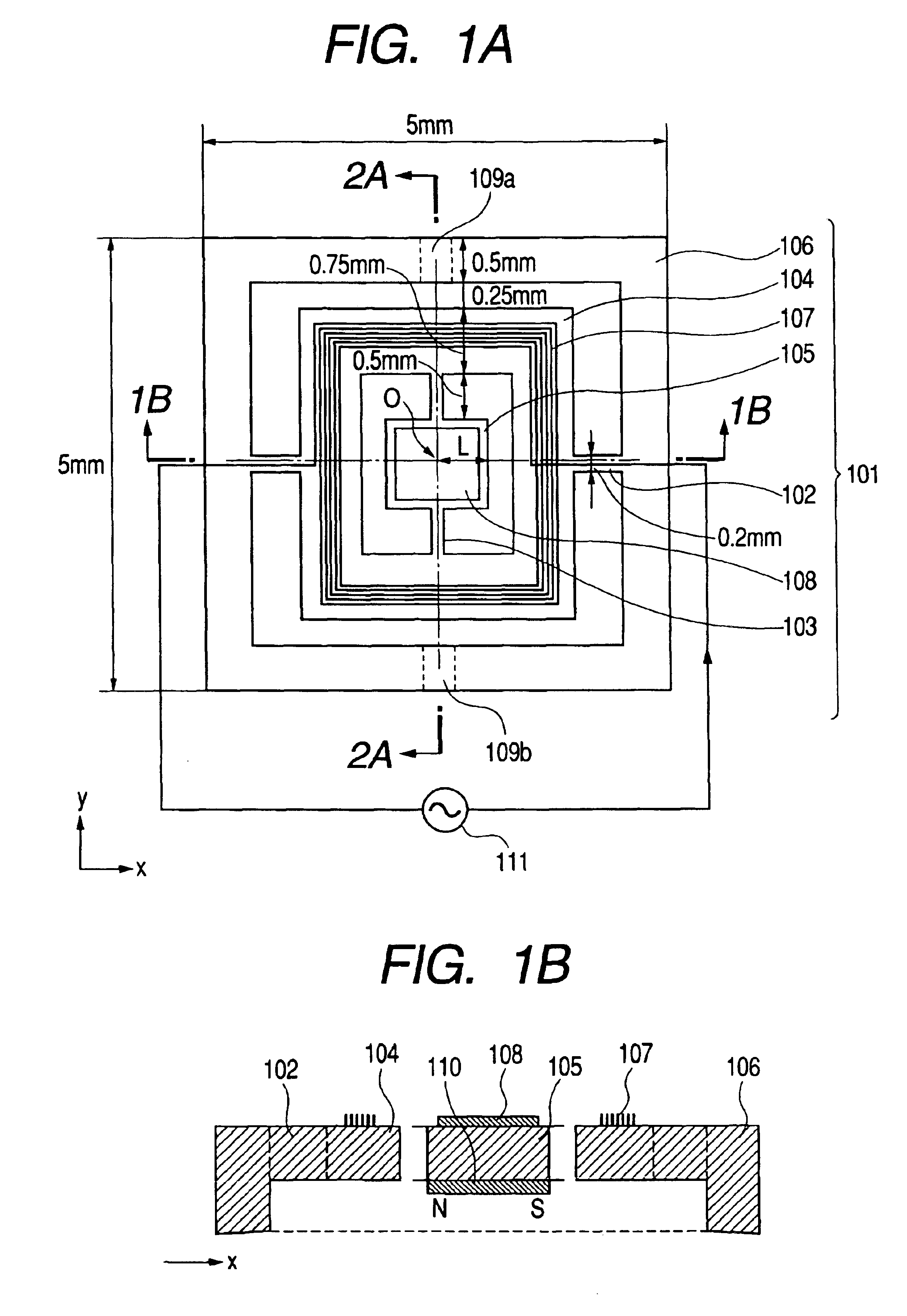
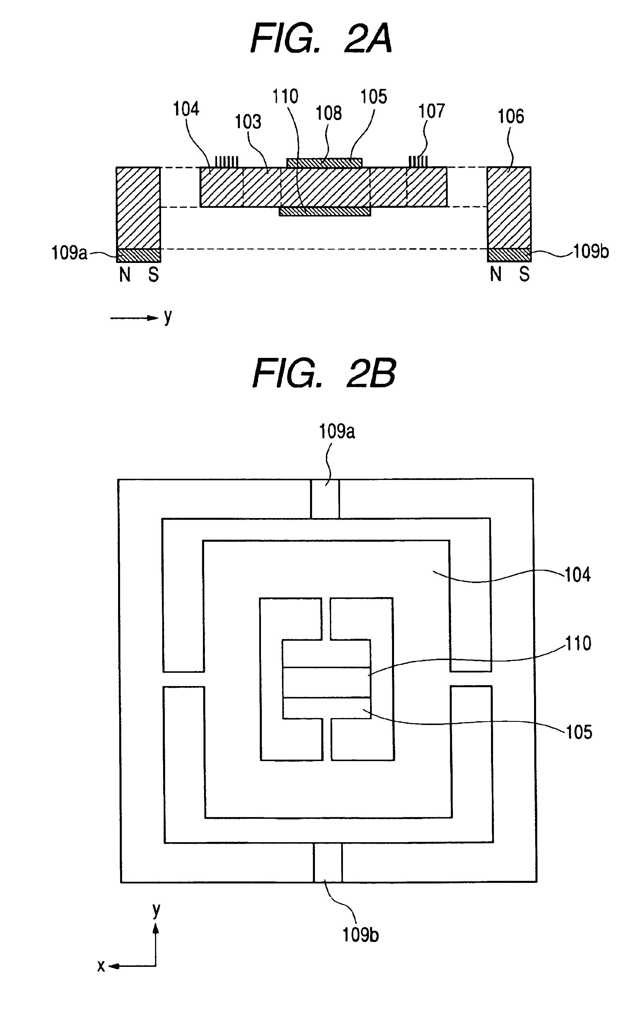
[0057]Example 1 of the-present invention will hereinbelow be described in detail with reference to FIGS. 1A and 1B, FIGS. 2A and 2B, and FIGS. 3A to 3H. First of all, a structure of Example 1 will now be described in detail. FIGS. 1A and 1B, and FIGS. 2A and 2Ba show a structure of an optical deflector according to this example. FIG. 1A is a plan view, FIG. 1B is a cross sectional view taken along the line 1B—1B of FIG. 1, FIG. 2A is a cross sectional view taken along the line 2A—2A of FIG. 1A, and FIG. 2B is a bottom view. In FIGS. 1A and 1B, and FIGS. 2A and 2B, reference numeral 101 designates the optical deflector a size of which is as shown in FIG. 1A. The supporting substrate 106 oscillatively supports the first movable plate 104 through the first torsion spring 102. In addition, the first movable plate 104 oscillatively supports the second movable plate 105 through the second torsion spring 103 orthogonal to the first torsion spring 102. A size of the second movable plate 105...

example 2

[0072]Next, Example 2 of the present invention will hereinbelow be described in detail. FIG. 4, and FIGS. 5A to 5C are respectively views useful in explaining an optical deflector according to Example 2 of the present invention. FIG. 4 is a plan view, FIG. 5A is a cross sectional view taken along the line 5A—5A of FIG. 4, and FIG. 5B is a cross sectional view taken along the line 5B—5B of FIG. 4. A basic structure, a driving method, a manufacturing method are substantially the same as those of above Example 1. In FIG. 4 and FIGS. 5A to 5C, reference numeral 201 designates an optical deflector; 202, a first torsion spring; 203, a second torsion spring; 204, a first movable plate; 205, a second movable plate; 206, a supporting substrate; 207a, a first coil; 207b, a second coil; 208, a deflection portion; 209a and 209b, first permanent magnets; 210, a second permanent magnet; 211a and 211b, current sources; 212, a cover; and 213, a supporting stage. In FIG. 4, for the purpose of making...

example 3

[0077]FIGS. 6A and 6B, and FIGS. 7A and 7B are respectively views useful in explaining an optical deflector according to Example 3 of the present invention. FIG. 6A shows a plan view, FIG. 6B shows a cross sectional view taken along the line 6B—6B of FIG. 6A, and FIG. 7A shows a cross sectional view taken along the line 7A—7A of FIG. 6A. A basic structure, a driving method, and a manufacturing method are substantially the same as those of above Example 1. In FIGS. 6A and 6B, and FIGS. 7A and 7B, reference numeral 301 designates an optical deflector; 302, a first torsion spring; 303, a second torsion spring; 304, a first movable plate; 305, a second movable plate; 306, a supporting substrate; 307a, a first coil; 307b, a second coil; 307c, a third coil; 308, a deflection portion; 309a and 309b, second permanent magnets; 310, a first permanent magnet; 314a and 314b, third permanent magnets; 311a, 311b and 311c, current sources; 312, a cover; and 313, a supporting stage. In FIG. 6A, for...


PUM


Abstract

Disclosed is an oscillation device comprising: a first movable plate adapted to be oscillated about a first rotation axis; a first elastic supporting portion for oscillatively supporting the first movable plate; a supporting substrate for fixing the first elastic supporting portion; a first magnetic field generating portion arranged in a position remote from the first movable plate; a second movable plate adapted to be oscillated about a second rotation axis; and a second elastic supporting portion fixed to the first movable plate for oscillatively supporting the second movable plate, in which a first coil is provided in the first movable plate to be turned round the second movable plate, and in which a second magnetic field generating portion is provided in the second movable plate. The oscillation device is capable of: operating at a high speed with large displacement; enhancing an energy efficiency; and oscillating about two axes.

Description

BACKGROUND OF THE INVENTION[0001]1. Field of the Invention[0002]The present invention relates to an oscillation device, an optical deflector using the oscillation device, and an image display device and an image forming apparatus using the optical deflector, and a method of manufacturing the oscillation device.[0003]2. Related Background Art[0004]In recent years, an electromagnetic actuator has been tried to be formed on a substrate made of silicon or the like by utilizing a semiconductor process. If the electromagnetic actuator is formed by utilizing the semiconductor process, a stator, a moving element and an electromagnetic coil can be collectively formed, and hence a process for joining and bonding is unnecessary. As a result, the stator, the moving element and the electromagnetic coil can be aligned with one another with high accuracy. In addition, since those elements can be formed on a massive scale at a time, reduction in cost can be expected.[0005]As one of examples of appl...

Claims


Application Information

Patent Timeline
Patent Type & Authority Patents(United States)
IPC IPC(8): B81B3/00G02B26/08
CPCB81B3/0018G02B26/085
Inventor HIROSE, FUTOSHISHIMADA, YASUHIROKATO, TAKAHISA
Owner CANON KK
Why Eureka
Try Eureka