

Gas turbine engine fuel/air premixers with variable geometry exit and method for controlling exit velocities
- Summary
- Abstract
- Description
- Claims
- Application Information
AI Technical Summary
Benefits of technology
Problems solved by technology
Method used
Image

Examples
first embodiment
[0153]FIG. 16 shows a gas turbine engine having combustion apparatus made in accordance with the present invention and using premixer apparatus variable exit geometry where the possible side effects of flash backs, flame instability, and / or impingement due to uncontrolled mixing tube exit velocities can be minimized or eliminated. It will be evident from the succeeding discussion that while the methods and apparatus of the present invention can advantageously and preferably be used with the previously described constructions that provide controlled fuel / air ratio mixtures for single stage combustion for gas turbine engines and gas generators, the present invention is not limited to such use.
[0154]Specifically, FIG. 16 shows a sectional view through gas turbine engine 1410 having compressor section (not shown) and turbine section 1416 operatively connected for rotation about engine axis 1418. Engine 1410 includes annular combustor chamber 1420, defined by liner 1422, with combustion ...
second embodiment
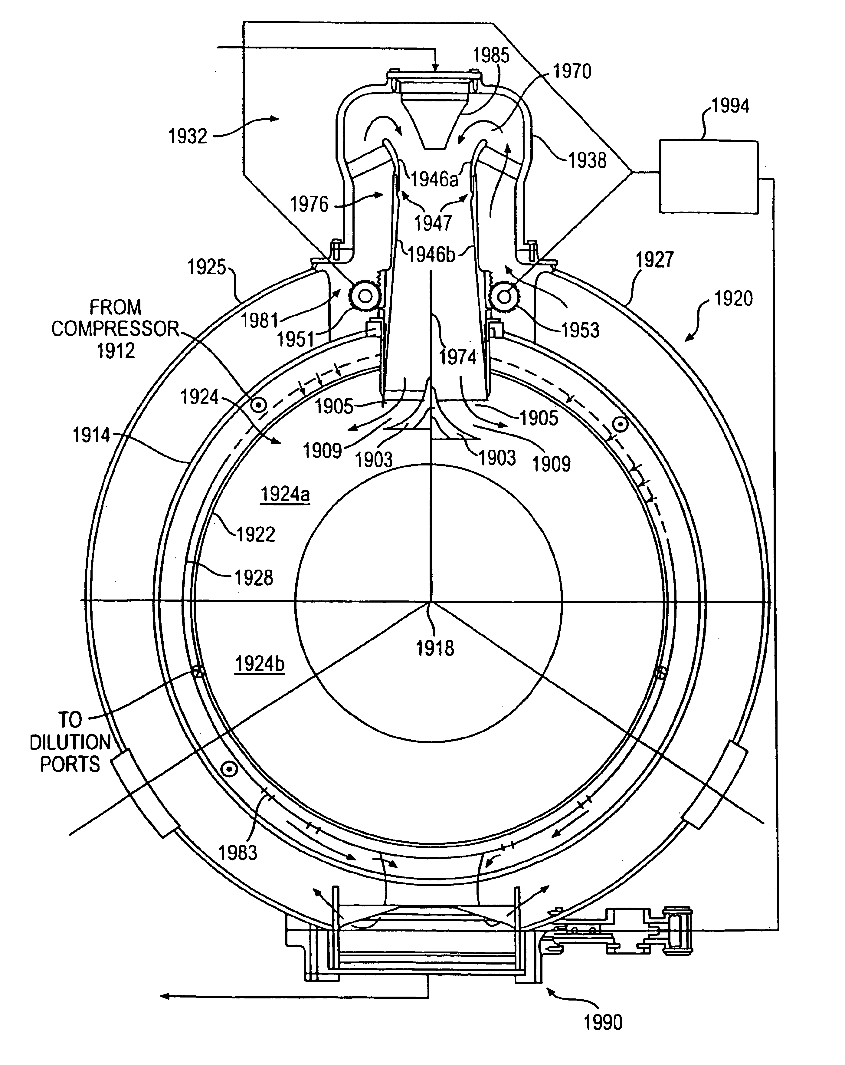
[0173]FIGS. 19A-19C depict the present invention of apparatus, combustor systems, and gas turbine engines utilizing a variable geometry mixing tube exit to control the fuel / air mixture velocity discharged into the combustor from a premixer. Specifically, FIG. 19A depicts a gas turbine engine 1910 with compressor section 1912, annular combustor 1920, and radial turbine 1916 situated similarly to the engine layout in FIG. 8. Engine 1910 includes a single premixer 1932 supplied with a controlled flow rate of compressed air for combustion from single air valve 1990 via a pair of manifolds 1925,1927 (only 1925 visible in FIG. 19A). As depicted in FIG. 19A, air valve 1990 is purposefully disposed at a diametrically opposed angular position relative to premixer 1932, for reasons that will be discussed later. While shown in FIGS. 19A-19C with a single premixer, the present invention nevertheless can be used with multiple premixers with a single or multiple air valves, and the premixers can ...
PUM
 Abstract
Description
Claims
Application Information