Devices and methods for applying known resistance loads and measuring internal angles of gyration in gyratory compactors

a compactor and gyratory technology, applied in the direction of mechanical means, instruments, manufacturing tools, etc., can solve the problems of inability to use typical sized specimens, molds used in many existing sgc models do not have enough volume to hold a typical size material specimen, and account for movement, so as to reduce the amount of preparation and improve operator safety and convenience. , the effect of reducing the potential for debris

a compactor and gyratory technology, applied in the direction of mechanical means, instruments, manufacturing tools, etc., can solve the problems of inability to use typical sized specimens, molds used in many existing sgc models do not have enough volume to hold a typical size material specimen, and account for movement, so as to reduce the amount of preparation and improve operator safety and convenience. , the effect of reducing the potential for debris

US6925889B2Inactive Publication Date: 2005-08-09PINE INSTR

Image

  • Devices and methods for applying known resistance loads and measuring internal angles of gyration in gyratory compactors
  • Devices and methods for applying known resistance loads and measuring internal angles of gyration in gyratory compactors
  • Devices and methods for applying known resistance loads and measuring internal angles of gyration in gyratory compactors

Examples


Embodiment Construction

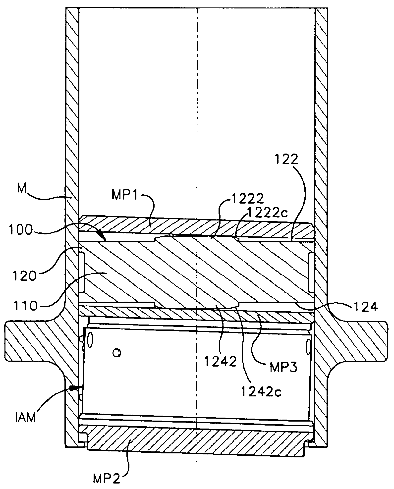
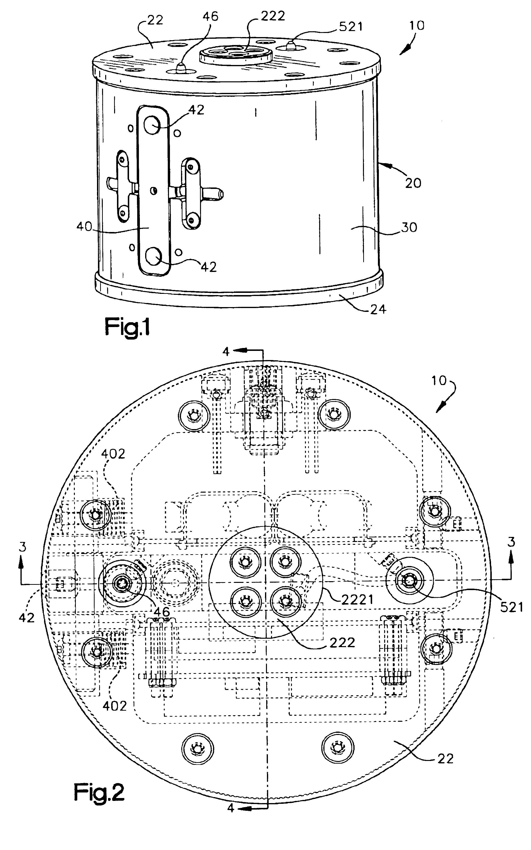
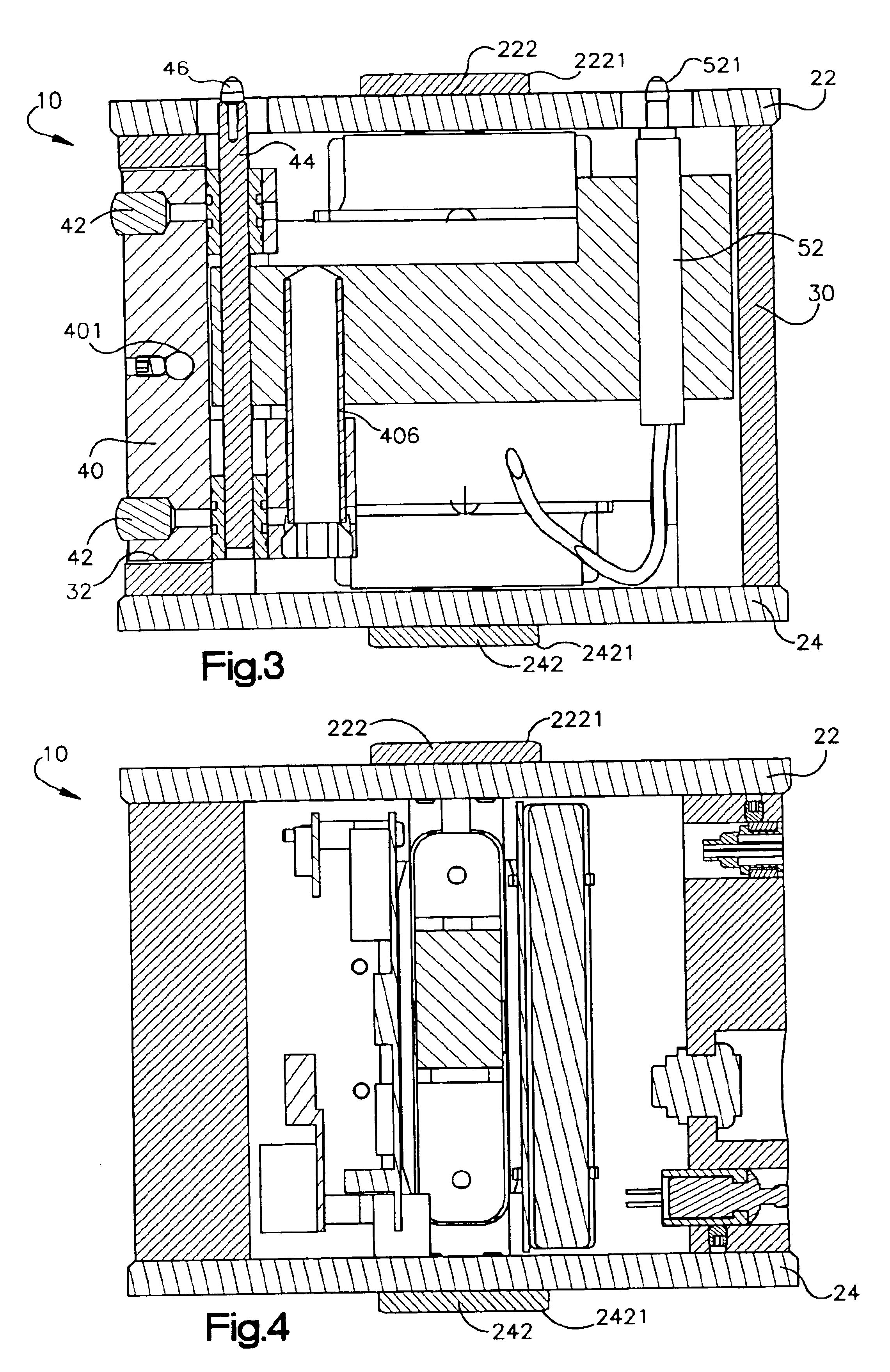
[0023]FIGS. 1-5 illustrate a first embodiment of an internal loading and internal gyration angle measurement device of the invention, indicated generally at 10. The device 10 in this particular form has a generally cylindrical body 20 which is generally configured to fit within a cylindrical mold of the type used in a gyratory compactor, such as a Superpave gyratory compactor. The body 20 of the device 10 can of course take different shapes and forms in relation to the mold in which it is to be used as described. In this embodiment, designed for use in a cylindrical mold M, as shown for example in FIG. 5, of the type used in Superpave gyratory compactors, the generally cylindrical body 20 is defined by circular end caps 22 and 24 with a wall 30 which extends between the end caps 22 and 24. Although shown in cylindrical form, the form of the wall 30 is not necessarily dictated by the form of the mold M, however in this instance the outside diameter of the wall 30 of the body is just ...


PUM

PropertyMeasurementUnit
Angleaaaaaaaaaa

Abstract

Devices and methods for providing a known resistance load and measuring an internal gyration angle of a mold in a gyratory compactor. A device in one form has a cylindrical body with protrusions through which a known resistance force is applied by the gyratory compactor, and probes which extend from the body to measure an internal angle of gyration of a mold within a gyratory compactor. The device is placed into a cylindrical mold which is placed into a gyratory compactor. Mold end plates may or may not be required depending on the gyratory compactor configuration and construction of the device body. As the mold is tilted on its axis to an operative gyration angle, the protrusions on each end of the body apply a moment force to the mold which produces a known resistance force on the gyratory compactor frame. Measurement of an internal angle of gyration is made while the resistance force is applied to the compactor frame and while the gyratory compactor gyrates the mold. The apparatus is then removed from the mold and the measured angle is obtained by connection to an external computer or directly read from the device. A display may be built into the body of the device to display the result directly. The components of the device inside the cylindrical body may be alternately arranged so that the angle measurement probes extend from the top or bottom or side wall of the cylindrical body. Use of an internal loading device in combination with an internal gyration angle measurement device is also disclosed. Use of an internal loading device in a gyratory compactor which is instrumented to measure an internal gyration angle external of the mold is also disclosed.

Description

RELATED APPLICATIONS[0001]This application is a conversion of U.S. Provisional Application Ser. No. 60 / 438,689, filed Jan. 8, 2003, and a continuation-in-part of U.S. application Ser. No. 10 / 273,864, filed Oct. 18, 2002.FIELD OF THE INVENTION[0002]This invention relates, in general, to the measurement of an angle of gyration in material testing equipment such as gyratory compactors, and to devices which simulate forces of materials which are tested by gyratory compactors.BACKGROUND OF THE INVENTION[0003]Gyratory compactors, including the SUPERPAVE Gyratory Compactors (SGC) developed in response to the Federal Highway Administration's SHRP research program, have proven to be a useful tool in the design and quality assurance programs for Hot Mix Asphalt (HMA) products. The SGC applies a constant consolidation pressure onto a material specimen, such as HMA, contained within a cylindrical mold of specified dimensions. The specimen is confined within the mold typically between two end pl...

Claims


Application Information

Patent Timeline
09 Aug 2005
Publication
US6925889B2
IPC
B29C43/04; B29C43/58; G01N3/08; G01N1/28; B29C43/36
CPC
B29C43/04; B29C43/58; G01N1/286; G01N3/08; B29C43/361; B29C2043/043
Inventors
PYLE, ROGER A.; DALTON, E. FRANK