Dental X-ray device comprising a mobile support structure

a mobile support and x-ray technology, applied in the field of dental x-ray devices, can solve the problems of one such path, and achieve the effects of improving the accuracy and efficiency of x-ray imaging, and improving the accuracy of x-ray imaging

Inactive Publication Date: 2005-08-09
SIRONA DENTAL SYSTEMS
View PDF9 Cites 57 Cited by
  • Summary
  • Abstract
  • Description
  • Claims
  • Application Information

AI Technical Summary

Benefits of technology

[0007]The advantage of the present invention resides in the combination of the separate bearing and guiding elements such that both rotational and translational movements are possible. Due to the fact that the bearing elements resting on the bearing face have freedom of movement and are thus non-guided, three directions of free movement are made available by a single bearing, ie movement in the horizontal directions to the right or to the left and forwards or backwards and also rotational movement about a vertical axis.
[0008]The structure of such a bearing is, compared with known systems using separated elements for rotation and translation, very much simpler and cheaper and still allows for precise and easy movement of the system even when of large mass, particularly when the bearing incorporates rolling elements which substantially roll on the bearing faces instead of sliding thereon.
[0009]It will be appreciated that this bearing may be in the form of a plain bearing, if desired, but this requires more powerful actuators on account of the higher frictional resistance involved.
[0010]A very exact and reliable system is obtained when the supporting structure to be moved is lightly clamped between two bearings. This is still distinctly less elaborate than is the case with prior systems. Furthermore, the stability and precision of this bearing is better than in prior systems, since in the latter case the bearing clearances and instabilities of the separate bearings and guide means summate.
[0011]The dental X-ray device may alternatively be designed such that an X-ray unit is mounted on a first movable supporting structure and the X-ray image detector is mounted on a second movable supporting structure, while both the supporting structure carrying the X-ray unit and the supporting structure carrying the X-ray image detector can be moved relatively to the stationary supporting structure.
[0012]The actuators for effecting horizontal movement can act directly on the rotation axis of the system or indirectly act thereon through an element coupled to the supporting structure to be moved, which element follows the instant center but does not follow the rotational movement of the supporting structure.

Problems solved by technology

A disadvantage in this case is that only one such path is possible.

Method used


Image

  • Dental X-ray device comprising a mobile support structure
  • Dental X-ray device comprising a mobile support structure
  • Dental X-ray device comprising a mobile support structure

Examples


Embodiment Construction

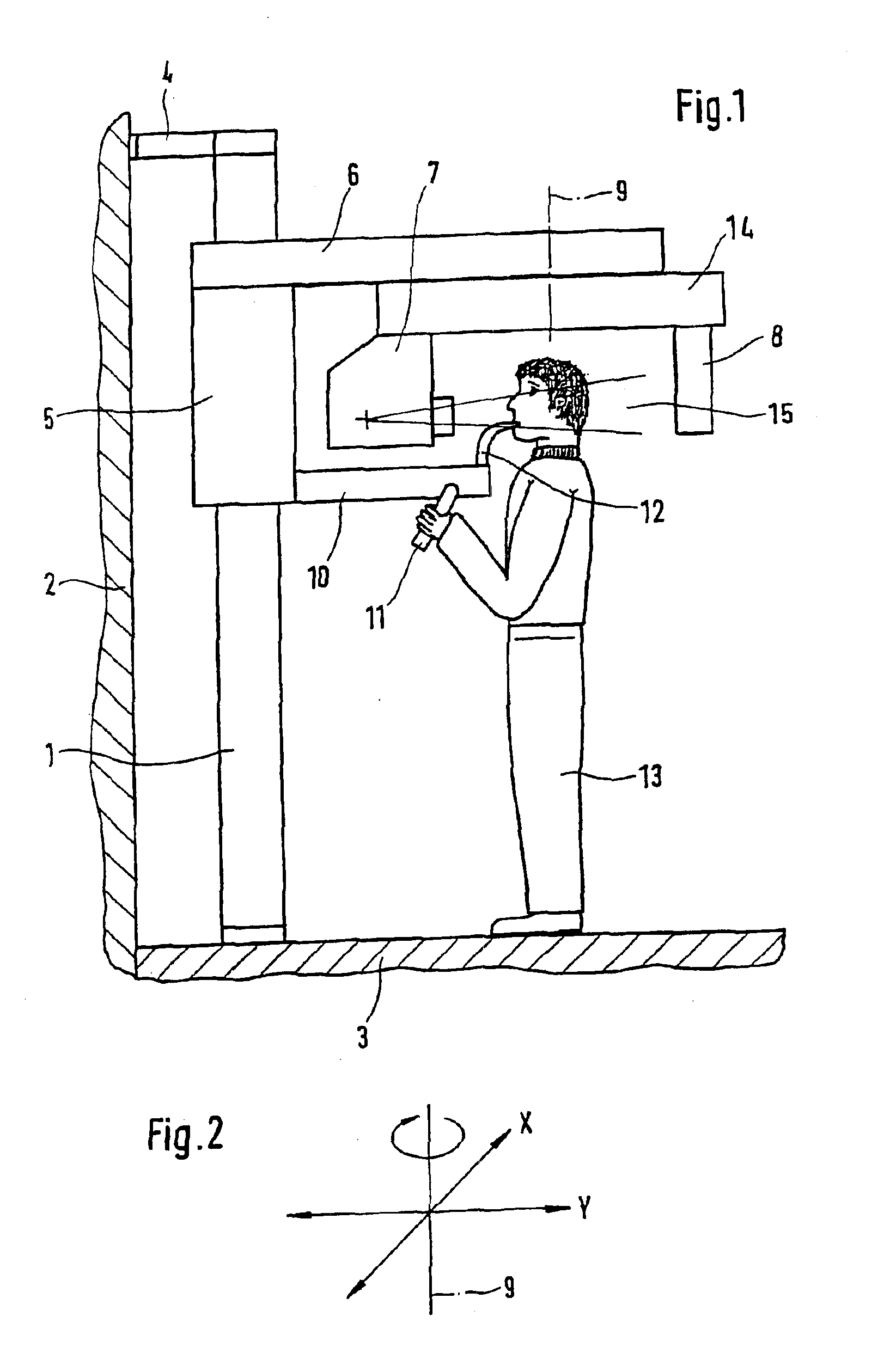
[0025]The X-ray device illustrated in FIG. 1 has a vertical supporting structure 1 spaced from a wall 2 and mounted at the bottom on a floor 3. Supporting structure 1 is secured at the top to wall 2 by means of a spacer 4. On this vertical supporting structure 1, also referred to as a column, there is mounted a horizontal, vertically adjustable supporting structure 5.

[0026]The detailed structure of such an X-ray device is described in detail in EP 0 229 308A1, as is also its mode of operation for making X-ray images. The embodiments disclosed in said application are included in full in this application by reference.

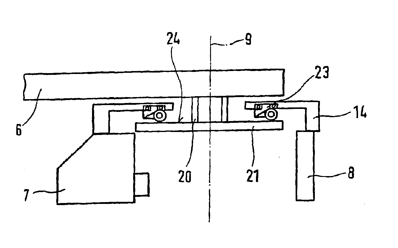
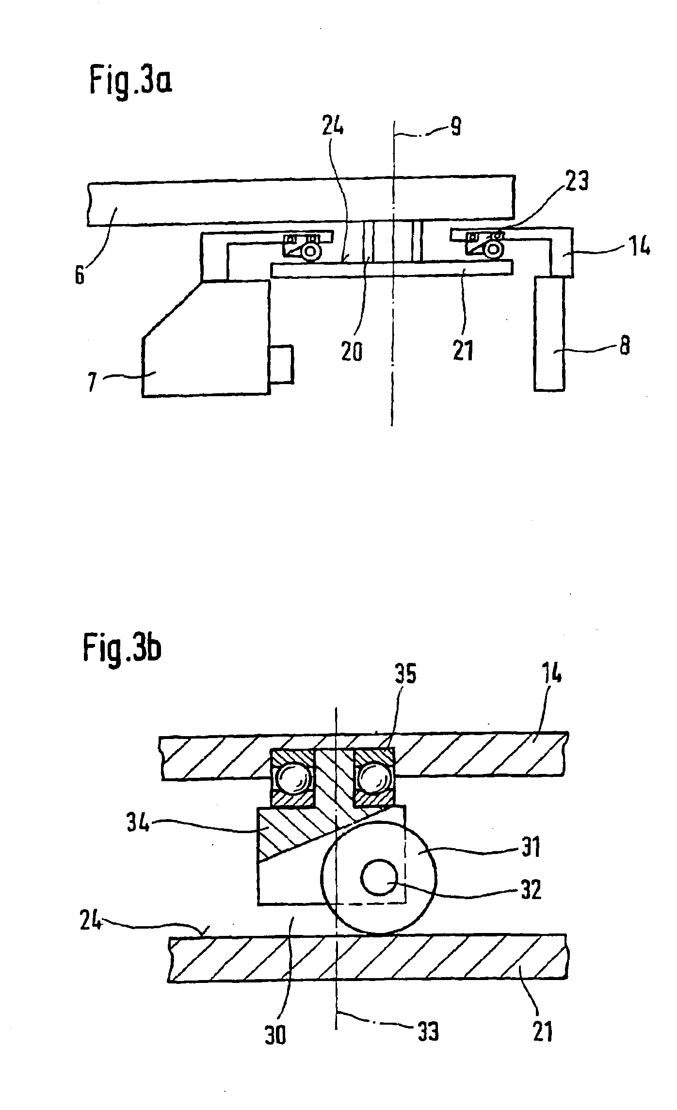
[0027]The horizontal supporting structure 5 is provided with a jib or holding arm 6, to which an X-ray unit 7 and an image detector 8 are attached for rotation about a longitudinal axis.

[0028]In order to position the patient, the horizontal supporting structure has, in addition, handles 11 and a mouthpiece 12 mounted on a holding arm 10, by means of which a patient 13 ret...


PUM


Abstract

The invention relates to a dental x-ray device comprising a mobile support structure for a system that can be displaced to produce x-ray photographs and also comprising a fixed support structure. The mobile support structure is displaceably mounted on the fixed support structure by one or more bearings. The device is provided with adjustment elements for the displacement of the support structure parallel to the bearing surface, in addition to a drive for carrying out a rotation of the support structure about an axis that is perpendicular to the bearing surface. The bearing elements are configured in such a way that they can be displaced on the bearing surface in every direction parallel to the bearing surface and can carry out a rotation about an axis that is perpendicular to the bearing surface.

Description

CROSS REFERENCE TO RELATED APPLICATION[0001]This is a continuation of International Application PCT / DE02 / 04108, fied Nov. 5, 2002, which designated the U.S. All priorities are claimed.TECHNICAL FIELD[0002]The invention relates to a dental X-ray device having a supporting structure for an X-ray system adapted to be movable for the purpose of making panoramic images, which should be understood to include panoramic radiograms and transverse tomographic images of the mandibular arch. Furthermore, said X-ray device can also be used for making cephalic images. The movable supporting structure is displaceably mounted on the stationary supporting structure by means of one or more bearings comprising bearing elements secured to at least one supporting structure. At least one supporting structure has a bearing face for the bearing elements. Regulating means are provided for displacing the supporting structure in a direction parallel to said bearing face. Furthermore, a drive is present for ef...

Claims


Application Information

Patent Timeline
Patent Type & Authority Patents(United States)
IPC IPC(8): A61B6/14
CPCA61B6/14
Inventor STOCKL, KLAUS
Owner SIRONA DENTAL SYSTEMS
Why Eureka
Try Eureka