Rotary machine housing with radially mounted sliding vanes

a rotary machine and sliding valve technology, which is applied in the direction of machines/engines, liquid fuel engines, applications, etc., can solve the problems of inadequate production of torque at the top dead center position, the position far removed from the radial housing does not lend itself to the use of sliding valve seals in general, and the method of displacing the gases contained within the minimum volume region or deriving power from this region with or without an external valve is not well understood. , to achieve the

Inactive Publication Date: 2005-08-09
SBAROUNIS JOASEPH A
View PDF15 Cites 29 Cited by
  • Summary
  • Abstract
  • Description
  • Claims
  • Application Information

AI Technical Summary

Benefits of technology

[0012]Another objective of the present invention is to provide a two lobe or multi-lobe rotary machine which greatly reduces the unusable volume at the minimum working volume while avoiding the effects of adverse expansion.
[0024]Another embodiment for the invention takes into consideration that the rotor surface can be cut such that the seals move towards the center of the chamber as the rotor approaches the position corresponding to the smallest volume region formed by the rotor apexes. A single seal between the high-pressure port and working volume can be used as a valve by constraining the seal from moving far enough to contact the rotor periphery for positions where the valve is wanted to be open. This would be instead of using multiple seals with a channel or mechanically lifting of the seal. There is an additional significance to having the seals moving inward as the rotor moves toward the top dead center position in that greater volume is displaced as the rotor approaches the top dead center. There is a very small working volume when the valve opens but the working volume from the previous cycle is still in an expansion or compression mode. The effect is to produce more even torque for all angles of rotation of the shaft.

Problems solved by technology

Henceforth, flow regulation for two-lobe or multi-lobe rotor rotary machines has represented one of the most challenging design considerations for construction of this type of machine for practical applications.
The concept of combining the trochoidal and cartiodal design seems to originate first with this patent however radially mounted seals were not well understood.
Positions far removed from this portion of the radial housing do not lend themselves to the use of the slidably mounted seals in general because of excessive total travel and pressure angles.
Additionally, a method of displacing the gases contained within the minimum volume region or deriving power from this region with or without an external valve or production of torque at the top dead center position has not been adequately achieved for this type of rotary machine.

Method used


Image

  • Rotary machine housing with radially mounted sliding vanes
  • Rotary machine housing with radially mounted sliding vanes
  • Rotary machine housing with radially mounted sliding vanes

Examples


Embodiment Construction

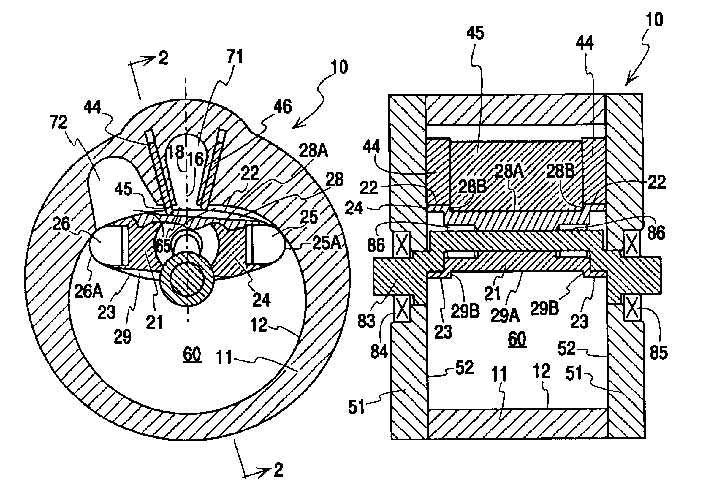
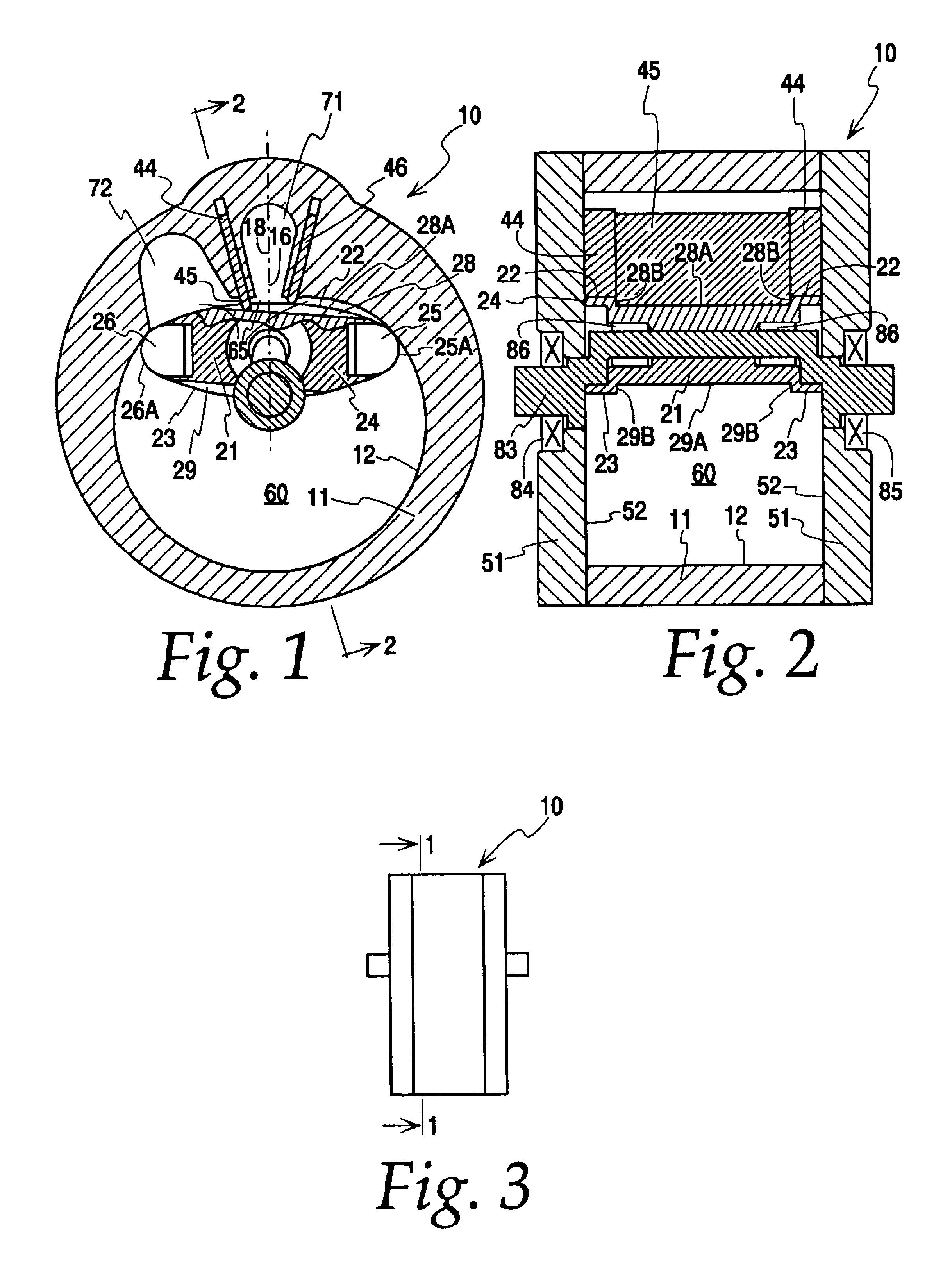
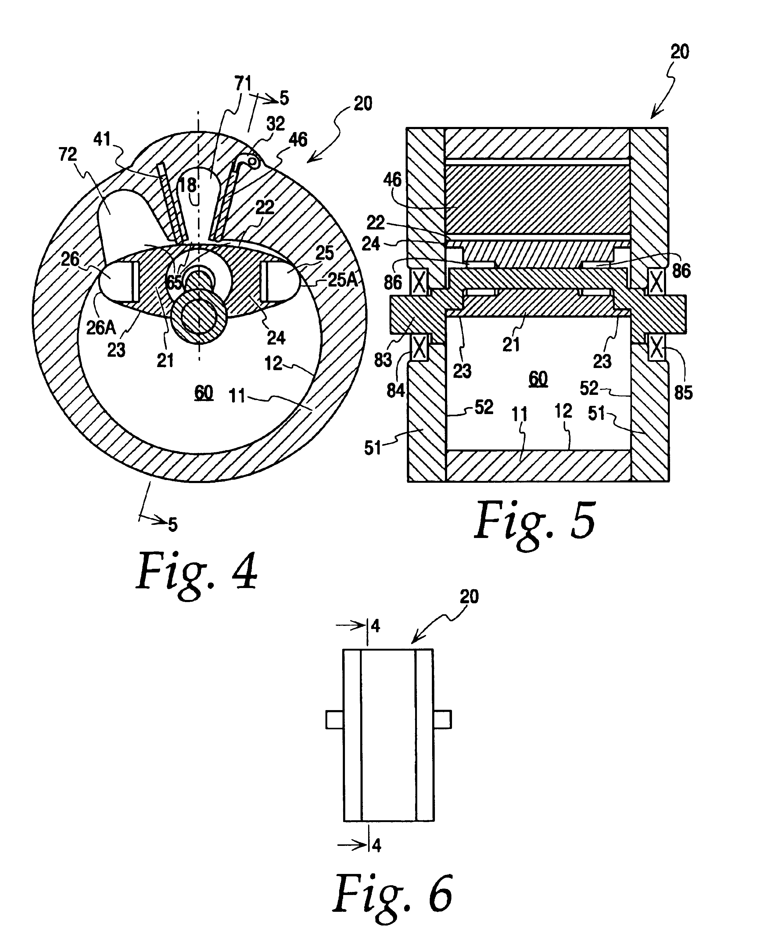
[0045]As will be seen herein, the present invention will be described with reference to a number of different rotary machines. Examples of rotary machines to which the present invention is directed, includes compressors and power expanders. As will be seen herein, the present invention has found immediate application to rotary machine housings defining a conventional internal cartiod cavity, with the rotor traversing, i.e., contacting the walls of the cartiod cavity. It will be readily appreciated by those skilled in the art that the present invention may be readily adapted to rotary machine housings having different internal cavity shapes, such as the two lobe rotor, three lobe Wankle type rotor, and multi lobe rotor.

[0046]Referring now to FIGS. 1-3, a first embodiment of a rotary machine according to principles of the present invention includes outer housing 11 having inwardly facing annular wall 12 and side housings 51 having inwardly facing end walls 52. The outer housing 11 and...


PUM


Abstract

Two or more slidably mounted seals of radially orientation are provided in a rotary machine. One of the slidably mounted seals can be selectably retractable to perform a valving operation with respect to a rotor mounted for eccentric rotary motion within the machine.

Description

BACKGROUND OF THE INVENTION[0001]1. Field of the Invention[0002]The present invention relates to the two-lobe and multi-lobe rotor rotary machine. More particularly, the present invention relates to the use of two or more slidably mounted seals of radial orientation located in the region of the center of the least volume portion that is formed between the rotor apexes in the housing chamber. The radial seals regulate and isolate working volumes within the machine by interaction with the periphery of the rotary piston. The advantages would apply to other epitroidal / epitrochial rotary machines and some advantages would apply to the broad class of trochoidal rotary machines.[0003]2. Description of the Related Art[0004]It is understood that many of the rotary piston machines represented by prior art can be used as a gas expandor. An example of this would be to power the device from high-pressure combustion gases or heated gases. In this context the rotary machine differs in function fro...

Claims


Application Information

Patent Timeline
Patent Type & Authority Patents(United States)
IPC IPC(8): F01C21/10F01C21/00F01C1/22F01C1/356F01C1/00
CPCF01C1/22F01C1/3566F01C21/106
Inventor SBAROUNIS, JOASEPH A.
Owner SBAROUNIS JOASEPH A
Why Eureka
Try Eureka